This thread has been locked.

If you have a related question, please click the "Ask a related question" button in the top right corner. The newly created question will be automatically linked to this question.

TAS5719: What are the causes of the Overcurrent (OC) Protection for TAS5719

Part Number: TAS5719

Hi TI Team,

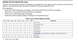
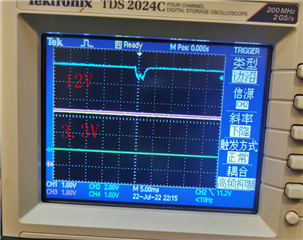
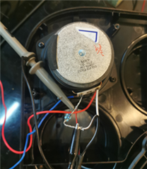
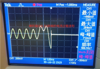
   we  use the TAS5719 to driver 2 speakers (4ohm 10W),when we play a overcharge digiti signal by IIS bus to the TAS5719,the gain for the speaker is only 10dB,it will cause the Overcurrent (OC) Protection With Current Limiting.

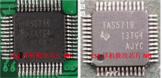
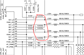
  What are the causes of the Overcurrent (OC) Protection for TAS5719? the register configuration? PCB Layout or other reason?

  I am looking forward to your help!

Tao

2022/7/20

  • Hi Tao

    when the current flow through the load exceed the over current threshold or output MOSFET bridge, the OC protection will be triggered.

    i think you can take a measurement of the output current at the output pin to confirm whether it exceed the OCthres or not.

    thanks.

    Jesse

  • Hi Jesse,

       Thanks for your response.

        we monitor the register 0x02  found the bit 2 is "1",it indicate the Overcurrent, overtemperature, overvoltage, or undervoltage error

      But we use another PCB to test this, it works normal, the difference is the normal board it 2 layers PCB and the error board is 4 layers.

      so we want to know the reason for the overcurrent? I hope you can provide some suggestions to fix this issue.

      Thanks a lot.

  • Zhang

    For there are four possible error happen, Can you help confirm below several things for analysis?

    1. does the voltage stable when error happen?(for judging overvoltage or under voltage)

    2. can you confirm does the chip thermal become very high when error happen? (to judge overtemperature)

    3. if you think it is OC trigger this problem, have you confirm the output current flow through the output? (to judge whether OC happen)

    "error happen at 4 layers PCB, not happen at 2 layers" this information is too less to analysis the root cause, the only possible reason maybe the thermal difference lead to this issue.

    thanks.

    Jesse

  • Hi Jesse,

       Please refer to my response:


    1. does the voltage stable when error happen?(for judging overvoltage or under voltage)

     RP:yes ,the volate is stable , please refer to the image below:

    2. can you confirm does the chip thermal become very high when error happen? (to judge overtemperature)

     RP: the temperature is not too high,when we firstlty play the audio,it will occur the protection.

    3. if you think it is OC trigger this problem, have you confirm the output current flow through the output? (to judge whether OC happen)

    RP: Actually we have not measure the output curretn flow, We do not have professional equipment, may not find the overcurrent,so we use exclusive method and speculate that it is overcurrent. so we want to know some reason for the overcurrent,we need some reference.

    we found the root reason is the TAS5719,Please refer to the image belwo, any suggestions?

    Thanks.

  • Hi Tao

    Can you give me your schematic for reference.

    Also, this situation also happen when the inductor of LC filter has large variance, so can you give me the specification of the inductor you customer use?

    thanks.

    Jesse

  • Hi Jesse,

       please refer to the sch file for reference.

       we use the 604010130 贴片电感 SWPA6045S150M T C83374_15UH±20% 2.05A 68MΩ 6*6mm SMD Sunlord inductor,please also refer to the spec.

      Thanks a lot.

    sch file:

    /cfs-file/__key/communityserver-discussions-components-files/6/TAS5719.pdf

    inductor spec:

    /cfs-file/__key/communityserver-discussions-components-files/6/SWPA6045S150MT-C83374_5F00_15UH_B100_20_2500_2.05A68M_A9035F00_2021_2D00_09_2D00_16.pdf


  • Hi Zhang

    I am afraid that the heat rating current of inductor customer use is a little small.

    can they take a try an inductor that Isat and Itemp are both high than 2.4A.

    the inductor our EVM board use is as below.

    Jesse

  • Hi Jesse,

       we have replace the inductor with 3A current,but it have not fix this issue.

      We use a method to measure the output current of the speaker,We add a small resistor in series at the output and then measure the voltage at both ends,the current is 1.79A(0.448V/0.25Ohm),the max current it 4.5A in the spec,please refer to the image below:  and the the same test in another 5719,it works normal,please comment on it,thanks.

  • Hi Zhang

    thank you very much for your measure.

    one thing need to confirm is that can customer change the BST cap to 0.1uF or larger?

    maybe it is caused by the un-enough charge to the BST cap.

    Maybe you can take a voltage measurement on the both side of BST cap when mute happen to confirm does its voltage is lower than 5V.

    thanks.

    Jesse

  • Hi Jesse,

      Thanks for your response,

      we have replace the cap to 0.1uf, but not fix this issue.

      Actuallty we have measure the voltage,you can refer to the image on above,they all normal.

    Thanks a lot!

  • Hi Zhang

    Here the voltage I mean the voltage at BST Cap, namely the voltage between BST_X and OUT_X. not the power supply.

    can you confirm 0.1uF and 0.033uF, the the voltage at the BST cap change or not, if no change, maybe much larger BST cap is necessary.

    like 0.33uF or 0.47uF.

    Please confirm

    thanks.

    Jesse

  • Hi Jesse,

       we will try to use lager BST cap and tell you the result later,thanks.