This thread has been locked.

If you have a related question, please click the "Ask a related question" button in the top right corner. The newly created question will be automatically linked to this question.

TLV320AIC3104: RIGHT_LOP/LOM output issue

Part Number: TLV320AIC3104


hi team:

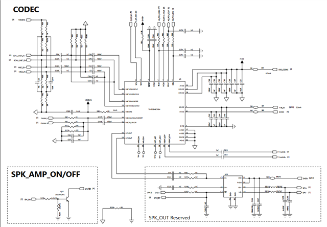
 we are using the TLV320AIC3104 to output a stable sound signal on RIGHT_LOM/LOP. Now RIGHT_LOP has sound output, and RIGHT_LOM has no sound output. I follow the documentation instructions as below:

 1.D7 of Register 89 and Register 92 is routed to DAC_L1/R1 stereo channel to RIGHT_LOP/LOM. By default, D7 of Register 92 is set to 1.
 2. Register 89 is set to 1, RIGHT_LOM still has no sound. 

If there are any registers to pay attention to? tks for you support!

  • Hi,

    I recommend using Figure 10-2 of the datasheet as a reference which I have shown here with your settings.

    You are actually mixing DAC left and DAC right into the Right Line differential output.

    I suggest use this diagram with the register map to configure the device per your need. Those characters in bracket is the register address in decimal for example (R89) is for register 89. I don't know what else was set in your register but Right Line output is a differential output (R93) so both should come out.

    Try configure the device using the above and if it's still not working then send me your register settings.

    Regards.

  • Hi pdjuandi:

     just check with customer , The data flow is shown as below. they use the PCM interface. When making a call, the audio stream flows from the dsp to the codec through the PCM interface. Now they want to play audio from differential output, but now RIGHT_LOP has sound, RIGHT_LOM has no output.

    if we follow up this dataflow ,do you have some recommendation?

    tks for your support !

  • Strange that it's only the P side is working and M side is not unless the pin is damaged. Is this only on 1 unit or all?

    I need to see the registers and let me know the MCLK, WCLK and BCLK frequencies also.

  • hi pdjuandi:

    tks for your comments. just check with customer this issue occurs at all the boards.

    and i attached the registers as below, hope you take a look. tks!

    AIC3104 config list.xlsx

  • Their register settings are incorrect, I have added the comment and my suggestion based on their path shown above.

    Now there are still things for them to check as this is coming from their host to match what's configured in this codec.

    • The audio interface DSP format, make sure that's what the host is sending refer to section 10.3.2.4 of the datasheet
    • The WCLK and BCLK coming from host is the correct frequency of 48KHz and 1.536MHz
    • The MCLK is tied to BCLK so we need to enable PLL to get the correct CODEC_CLK frequency

    4426.AIC3104 config list.xlsx

    Regards.

  • hi pdjuandi:

     Just check with customer, the sync of the  host can only be 16Khz/8Khz. So would you help to recommend the latest registers base on the fsref=16 KHz?

  • Here is 16KHz DAC Fs setting.

    5618.AIC3104 config list.xlsx

    Regards.

  • hi pdjuandi:

     Tks for your support, your config file works well in customer board.

     but for the further test. the customer want to set the volume output Vpp as 1.2V, but when we set the DAC vol as 0X7f ,just get 300mV,

     so as i see , 127gain ->DAC 0x7f. =>300mV

     another test is 63 gain -> Dac 0x33 =>50mV

    do we have another register to for further check? tks!

  • Did you get 4Vpp with 0db Right-DAC volume and 0dB RIGHT_LO output level at RIGHT_LO differential output?

    I suggest start from the top, make sure you are providing the right input and check the output are correct with 0dB. Then you can start reducing the DAC volume gain.

    The above gain changes from 0x7F to 0x33 does not make sense. 0x7F reduces the signal by 63.5dB and 0x33 reduces by 25.2dB, but the data shows otherwise.

  • hi pdjuandi:

     tks for your comments. we just follow your method and fixed. But we found another issue from the MIC path.

    as below B/D, we connect the FM signal with MIC pin14,16. you know , the FM sometime will have noise, so we change the PGA Capture volume as 0, it can eliminate the noise ,but sometime we found that there is no sound come into the MIC part. it may be cause by the PGA setting . 

    would you share some suggestion to decrease the noise from the FM ? tks ~

  • Are you saying the input source (FM) itself is noisy in your statement "the FM sometime will have noise" and you want to remove the noise?

    When you said change volume to 0, are you referring to changing volume gain to 0dB or no volume (mute)?

    No volume or mute will result to no output so you will not hear anything, but 0dB gain means no gain or attenuation but you will hear whatever is of the input.

  • HI pdjuandi:

    tks for your feedback.

    Are you saying the input source (FM) itself is noisy in your statement "the FM sometime will have noise" and you want to remove the noise?

    yes, we want to remove the noise which comes from FM. and have better signal at the end terminal part.

    When you said change volume to 0, are you referring to changing volume gain to 0dB or no volume (mute)?

    we are changing the programmable gain amplifier (PGA) to 0db, which it is work. but sometime the normal signal output also disappear.

    No volume or mute will result to no output so you will not hear anything, but 0dB gain means no gain or attenuation but you will hear whatever is of the input.

    get it ,it seems that the customer have some misunderstanding of the PGA setting ,we should hear everything without gain or attenuation.

     but besides the gain setting ,do want have some common ways to reduce the noise?

  • If the source itself is noisy, this device does not have DSP capability to remove the noise. 

    You will need noise cancellation algorithm in DSP to achieve that.

    In this register, setting bit D7 to "1" will mute the signal, so they need to set it to "0", no signal recorded can be caused by the source itself or clocks are missing. The codec is slave mode so make sure the host are providing the clocks continuously.

  • hi  pdjuandi::

     tks for your comments, it was clearer before.

     as i check with the customer, some change of the MCLK as below, customer set the BCLK separately. Base on the R102, we try to set 0xA2 but come without output. 

     but 0X82 and 0X22 works, can you share your comments?

    7416.AIC3104 config list.xlsx

  • For more details sharing from customer:

     The results of the test here are as follows:

    1. In the process of making a phone call or listening to the FM radio, if the register 102 is changed to 0x82, there is a sound, and there is no sound at 0x02 and 0x22 setting.

    2. The register is changed to 0x82, and the mobile terminating call start the speak, and then echoes can be heard on the mobile terminating call side, and when the FM radio is playing at the same time, the radio also has echoes too.

    regarding to the echo, do you think the input signal are some how mix together?

  • Using this clock diagram, setting R102 to 0x82 means you are setting the CLKDIV_IN to use BCLK and PLLCLK_IN to use MCLK.

    Setting it to 0x22 means you are setting the CLKDIV_IN to use MCLK and PLLCLK_IN to use BCLK and setting it to 0xA2 means both CLKDIV_IN and PLLCLK_IN are using BCLK.

    So in your use case you need to use PLL and since your MCLK is physically tied to BCLK either R102 D5-D4 00 or 10 is fine. 

    Did you modify the configuration I sent or are they the same? Your 0x82 setting is without PLL and the noise/echo is because of wrong configuration.

    You might want to capture the MCLK/BCLK and WCLK on the scope and let me see.

  • Hi pdjuandi:

     the customer just have some modification on the MCLK part ,which connect to GND. and i attached the latest register list and waveform as below, can you help to support the echo issue? tks ~

    9-7 AIC3104 config list.xlsx

  • Are you saying they connect MCLK to GND? MCLK needs to be provided to codec.

    Please check your registers, I suggest just test with 1 output path right now either HP or LINE and use the same DAC path.

    I see you have DAC_L1 to LINE and DAC_R3 to HP.

    Another observation is you have 1 clock offset, please cross check what's the host is sending and make sure it's correct with the scope.

    0284.9-7 AIC3104 config list.xlsx

  • Yes, as shown below:

    1. MCLK is connected to GND through 100nF.

    As I can see, customers think they can set R102 to 0xA2, so CLKDIV_IN and PLLCLK_IN use BCLK and don't need MCLK, do you mean this is not recommended?

    And also the customer set the R102 initial value is 0x02 when is calling, if playing the radio will set the PCM hardware interface, and set R102 to 0xa2,do you think it is okay with that if base on the customer circuit

  • As long as they set the register to use BCLK that's fine.

    They can start with 0xA2.

  • Hi pdjuandi:

    Please check your registers, I suggest just test with 1 output path right now either HP or LINE and use the same DAC path.

    I see you have DAC_L1 to LINE and DAC_R3 to HP.

    As you mentioned about this topic, i ask customer try to set the same path of DAC L1 with DAC R1, and here is the result test by customer:

    Switch the DAC to DAC_R1/L1:

    1.Play the FM radio, it will take 5-6s to have a sound output.
    2. To make a call as a caller:
    1). The volume of DAC_R1/L1 becomes smaller, and the sound will not be released from the power amplifier.
    2). While making a phone call and playing the FM radio, the human voice will be played from the speaker.
    3). the mobile terminating call can't hear the echo now . 
    3. Hang up the phone after the call is finished, and the voices of the people around you will still be played in a small voice from the speaker.

     Under the condition of DAC_R1/L1, changing R10 to 0x00 has no effect on the test effect.

    hope you can give me some guidance ,tks~

  • I'm not clear what the issue is now.

    Are you saying it is working now and the only thing left is the voices of the people around that is picked up and send to speaker?

    If the ADC path is powered up, the MIC input obviously can pick up any sound.

  • hi  pdjuandi : 

     sorry for the inconvenience, i am try to make you clearly and for me side to understand the logic of the register setting.

    Play the FM radio, it will take 5-6s to have a sound outpu

    regarding this issue, the FM comes from pin14 16 (MIC2L/R)and output from pin 29 30(RIGHT_LOM/P).

    So i think we should use DAC_L1 and R1 as Figure 10-16 mentioned: If instead the DAC analog output must be routed to multiple output drivers simultaneously (such as to LEFT_LOP/M and RIGHT_LOP/M) or must be mixed with other analog signals, then the DAC outputs should be switched through the DAC_L1/R1 path.

    5618.AIC3104 config list.xlsx

    But base on the previous config list you provide. you set the R41 to 0X51, which means the Left_DAC=DAC_L3, Right_DAC=DAC_R3. but i think the LEFT_LOP/M  and RIGHT_LOP/M are separate channel to output  different audio signal. Can you help to share your suggestion? tks 

  • Is the FM input a stereo SE input or mono differential input? You are connecting the input to stereo input (MIC2L/R) but wanted the output only on RIGHT_LINE differential output. 

    DAC_L3/DAC_R3 are what they have set from their initial settings, they can change to DAC_L1/R1 if that's what they want.

    Again I suggest they used the block diagram and map out their path as I think there's some confusion with their path.

  • hi pdjuandi : 

     tks for your explanation. i think we make more clear in this codec now.

     and there is another issue relate to the switching input source.

     the customer set the MIC input as PIN 12 .13

     set the FM input as PIN 14 16.

     so the working logic is picking one of two between FM and MIC.


    so the registers are as follow:

     MIC open, FM close:

     R17=0XFF

     R18=0XFF

     R21=0X00

     R22=0X00

    MIC close, FM open:

    R17=0X0F

    R18=0XF0

    R21=0111 1000

    R22=0111 1100

    Base on this logic, we found the when using the FM, we still can hear the voice from MIC,  i think there maybe some register is missing to block the MIC into the FM signal.

     tks for your guide!

  • Here are the proposed settings, the definition of open switch means path is not active and close means path is active.

    The settings provided above are opposite.

    This is what I see they want to configure the codec but please confirm with them and change if needed.

    • MIC (MIC1RP/M to Right ADC) open, FM (MIC2L to Left ADC and MIC2R to Right ADC) close case:
      • P0 R17: 0x0F
      • P0 R18: 0XF0
      • P0 R19: 0X7C
      • P0 R21: 0x78
      • P0 R22: 0x7C
      • P0 R24: 0x78
    • MIC (MIC1RP/M to Right ADC) close, FM (MIC2L to Left ADC and MIC2R to Right ADC) open case:
      • P0 R17: 0xFF
      • P0 R18: 0XFF
      • P0 R19: 0X7C
      • P0 R21: 0x78
      • P0 R22: 0x84
      • P0 R24: 0x78

    Regards.

  • hi pdjuandi : 

    tks for your reply. as i see ,there is a confusion for the MIC close ,FM open case.

    MIC (MIC1RP/M to Right ADC) close, FM (MIC2L to Left ADC and MIC2R to Right ADC) open case:
    • P0 R17: 0xFF
    • P0 R18: 0XFF

    regarding this setting ,i can see the FM signals( MIC2L/R) are both not connected to the L/R ADC PGA, why do we call the FM open?

  • FM open means we are not connecting the FM (MIC2L and MIC2R) path to ADC only the MIC1RP/M is active.

    See my definition above.

    P0 R17: 0xFF