Hi,
I have two questions for TAS5825PEVM.
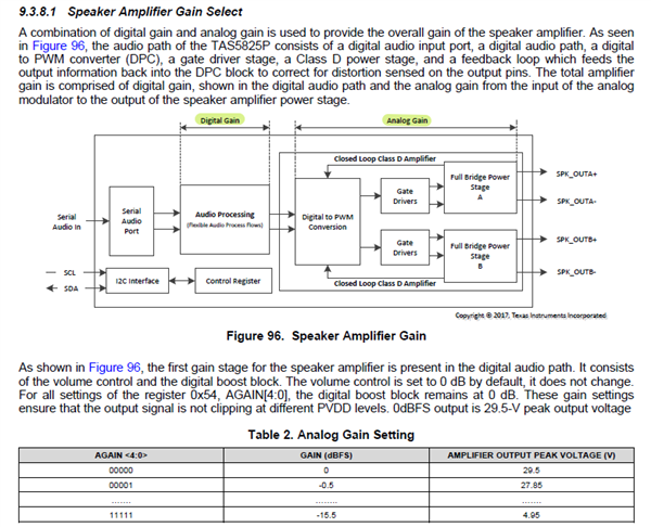
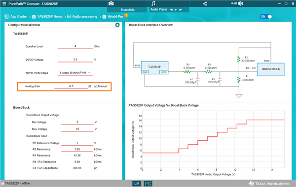
1. TAS5825PEVM used LM5155D GPIO1_Hybrid_Pro to adjust output voltage?
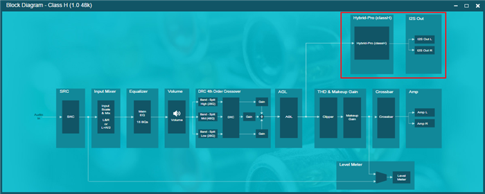
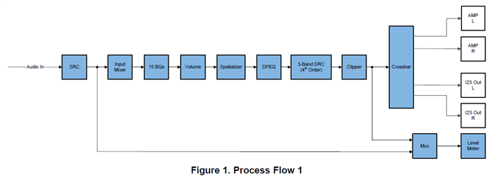
2. Does there have TAS5825PEVM process flow can share to me?
Thanks!
Jeff
Hi,
I have two questions for TAS5825PEVM.
1. TAS5825PEVM used LM5155D GPIO1_Hybrid_Pro to adjust output voltage?
2. Does there have TAS5825PEVM process flow can share to me?
Thanks!
Jeff