


Hello, Team,
While the software in their system is still under development, customer would like to try TPA6304-Q1 without it.
- They tried to turn-on the device by putting the STANDBY pin to Hi, but did not see any output.
Are there any diagnostic or other features that is required for the device to operate?
Or, does STANDBY should not go Hi with VBAT&PVDD?
When taken look at the sequence, I see STANDBY going Hi after other pins going Hi/Lo: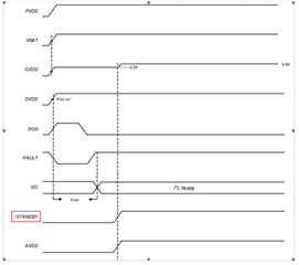
- Can we try the software in the TPA6304-Q1EVM and the PPC to turn-on the TPA6304-Q1 in the customer board?
In that case, can we control TPA6304-Q1 in the customer's board via I2C signal?
If so, which is need to be connected: SCL, SDA, as well as STB and DIAG?
If it is difficult to control/turn-on TPA6304-Q1 in either 1 or 2 above, they will wait for the software development.
Could you please help us out here?
Best Regards,
Masaru
