This thread has been locked.

If you have a related question, please click the "Ask a related question" button in the top right corner. The newly created question will be automatically linked to this question.

TLV320AIC3254

Other Parts Discussed in Thread: TLV320AIC3254EVM-K

Hi,
 
I'm working with TLV320AIC3254EVM-K mounted on USB-MODEVM INTERFACE board.
My main goals are:
1) Sampling and decimation of an analog input signal from IN1(L and R - J2) by the AIC ADC's.
2) Compression of the decimated signal by miniDSP's (A-LAW copression) and forwarding the compressed
    signal to Digital output (Dout pin). 
3) Simultaniously the digital signal from digital input (DIn pin) should be decompressed by miniDSP's (A-law)
    and interpolated by the DAC's, then this signal will be forwarded to analog output LINE OUT(LOL,LOR - J6).
 
However I'm stacked in very basic.
 
Could you please assist me to solve the following issue:
 
My input signal is 1Vp-p and 2hz (connected to IN1) and the AIC configured
to support the following inner chain IN1 -> ADC -> miniDSP_A ->miniDSP_D ->DAC -> LINE OUT. 
In Line Out I'm expecting to get the same signal as was in the input, however the output is constant 0.9V DC
(Is it "common mode voltage"?), i.e. the signals do not pass to the outputs.
 
I was trying to configure the AIC with the AIC3254 CS tool and the by the PurePath studio. 
 
In the AIC3254 CS software in the upper area we see:
   AIC3254 CS was recognised by my EVM-Board. 
   FIRMWARE NAME: USB-miniEVM
   VERTION; 2.03
   USB INTERFACE: I2C FAST
   I2C ADRESS: 0x30
 
The configuration in the software is as follows:
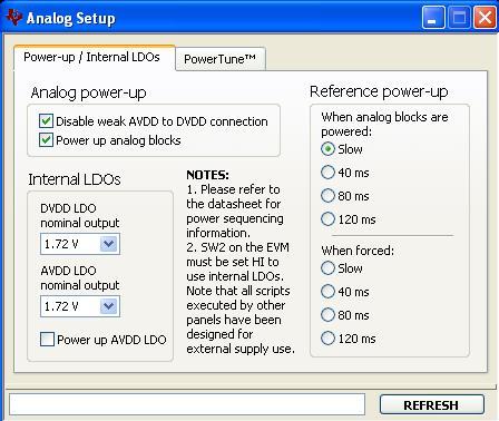
ANALOG SETTING:
           ANALOG SETUP- see Figure 1.
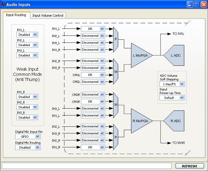
           AUDIO INPUTS :
                   INPUT ROUTING - see Figure 2a.
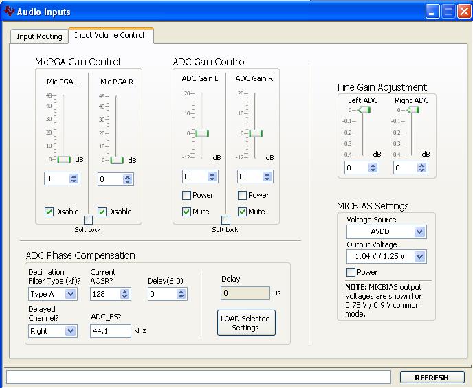
                   INPUT VOLUME CONTROL - see Figure 2b.
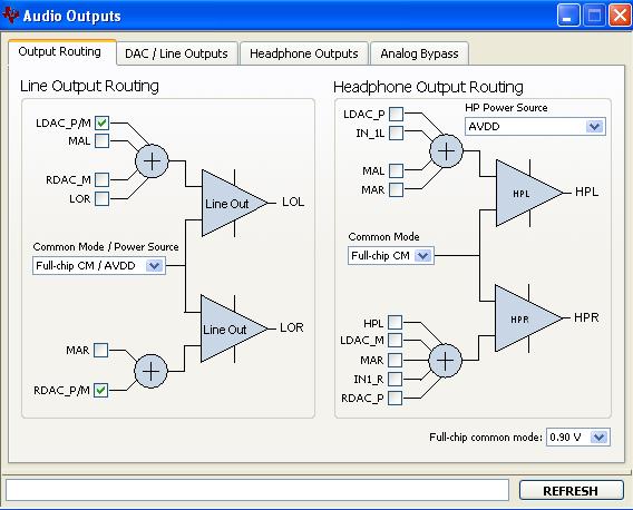
           AUDIO OUTPUTS:
                   OUTPUTS ROUTING - see Figute3a.
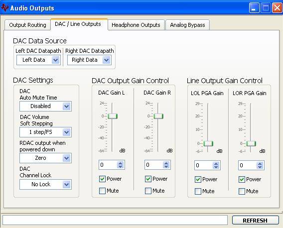
                   DAC/Line Outputs - see Figure 3b.
                  
Configuration USB-MODEVM BOARD:
   SW2 : 1,3,4,5,6,7 -ON , 2,8-OFF
Configuration TLV320AIC3254EVM-K :
  SW1 : I2C
  SW2 : LOW
 
 
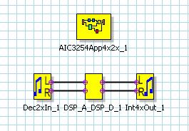
With PurePath Studio (see Figure 4):
Registers map is attached - please see ProcessFlow1


Please advise how to proceed with the current project.
 
Thank you in advance!
Shlomi
  • ###############################################
    #
    # For use with the following firmware image:
    # ..\image\USBMODEVM0200_48KHZ.BIN
    #
    # This script configures both ADC and DAC
    # channels for line-in and headphone
    # monitoring.
    #
    # An analog loopback test can be performed by
    # connecting a 1/8" male to male cable from
    # J10 (Headphone Test) to J1 (IN1).
    #
    ###############################################


    ###############################################
    # Software Reset
    ###############################################
    #
    # Select Page 0
    w 30 00 00
    #
    # Initialize the device through software reset
    w 30 01 01
    #
    ###############################################


    ###############################################
    # Clock and Interface Settings
    # ---------------------------------------------
    # The codec receives: MCLK = 12.288 MHz,
    # BLCK = 3.072 MHz, WCLK = 48 kHz
    ###############################################
    #
    # Select Page 0
    w 30 00 00
    #
    # PLL_clkin = MCLK, codec_clkin = PLL_CLK,
    # PLL on, P=1, R=1, J=8, D=0000
    w 30 04 03 91 08 00 00
    #
    # NDAC = 2, MDAC = 8, dividers powered on
    w 30 0b 82 88
    #
    # DOSR = 128
    w 30 0D 00 80
    #
    # NADC = 2, MADC = 8, dividers powered on
    w 30 12 82 88
    #
    # AOSR = 128
    w 30 14 80
    #
    ###############################################


    ###############################################
    # Configure Power Supplies
    ###############################################
    #
    # Select Page 1
    w 30 00 01
    #
    # Disable weak AVDD in presence of external
    # AVDD supply
    w 30 01 08
    #
    # Enable Master Analog Power Control
    w 30 02 00
    #
    # Set the input power-up time to 3.1ms (for ADC)
    w 30 47 32
    #
    # Set the REF charging time to 40ms
    w 30 7b 01
    #
    ###############################################


    ###############################################
    # Configure Processing Blocks
    ###############################################
    #
    # Select Page 0
    w 30 00 00
    #
    # PRB_P2 and PRB_R2 selected
    w 30 3C 02 02
    #
    ###############################################


    ###############################################
    # Configure ADC Channel
    ###############################################
    #
    # Select Page 1
    w 30 00 01
    #
    # Route IN1L to LEFT_P with 20K input impedance
    w 30 34 80
    #
    # Route CM1L to LEFT_M with 20K input impedance
    w 30 36 80
    #
    # Route IN1R to RIGHT_P with 20K input impedance
    w 30 37 80
    #
    # Route CM1R to RIGHT_M with 20K input impedance
    w 30 39 80
    #
    # Unmute Left MICPGA, Gain selection of 6dB to
    # make channel gain 0dB, since 20K input
    # impedance is used single ended
    w 30 3b 0c
    #
    # Unmute Right MICPGA, Gain selection of 6dB to
    # make channel gain 0dB, since 20K input
    # impedance is used single ended
    w 30 3c 0c
    #
    # Select Page 0
    w 30 00 00
    #
    # Power up LADC/RADC
    w 30 51 c0
    #
    # Unmute LADC/RADC
    w 30 52 00
    #
    ###############################################


    ###############################################
    # Configure DAC Channel
    ###############################################
    #
    # Select Page 1
    w 30 00 01
    #
    # De-pop: 5 time constants, 6k resistance
    w 30 14 25
    #
    # Route LDAC/RDAC to HPL/HPR
    w 30 0c 08 08
    #
    # Power up HPL/HPR
    w 30 09 30
    #
    # Unmute HPL/HPR driver, 0dB Gain
    w 30 10 00 00
    #
    # Select Page 0
    w 30 00 00
    #
    # DAC => 0dB
    w 30 41 00 00
    #
    # Power up LDAC/RDAC
    w 30 3f d6
    #
    # Unmute LDAC/RDAC
    w 30 40 00
    #
    ###############################################

    Shlomi,

    The 0.9V common mode is normal and expected.

    Please run the attached script in AIC3254 CS using the command line interface. Once executed, route the DACs to the lineouts and power and unmute the lineout amplifiers. Then, enable digital loopback, which basically routes the ADC data to the DAC input. It should now be working.

    In PurePath, please use the 8x4x framework for sample rates 48ksps and below. If you want to use the 4x2x interpolation/decimation filters, you need to modify the SystemSettingsCode property of the framework for an AOSR = 64.


    Regards,

    J-

  • Hi J Arbona,
     
    I want to thank you for your helping. The problem was solved.

    I have another question about PurePath Studio:
     
    For our project we must achieve compression rate of a sampled voice as low as G.726 standard (32Kbit/Sec).
    We know that current version of PPS supports A-Law and U-Law encoding/decoding blocks.
    This algorithms using G.711 standard for audio compression. Thus, 64Kbit/Sec bitstream for a signal sampled at 8 kHz. 
    How can we implement G.726 standard in PPS. Did someone implemented G.726 standard in PPS ,
    or another algorithm with the same low bitstream (32KHz)?
    Thanks,
    Shlomi

  • Hi Shlomi,

    Sorry, we do not support ADPCM in our miniDSP devices. U-law and A-law will give the lowest sample size we can provide at 8-bits per sample at the desired sample rate.

    Regards,

    J-