This thread has been locked.

If you have a related question, please click the "Ask a related question" button in the top right corner. The newly created question will be automatically linked to this question.

TAS5720A-Q1: No Audio, CLKE bit Error Fault Pin Pulsing Persistently

Part Number: TAS5720A-Q1

Hi,

We are using TI's Automotive Class-D Audio Amplifier 'TAS5720ATDAPQ1' and the controller we are using is ATMEL's 'ATSAMV70Q20B-AAB'.
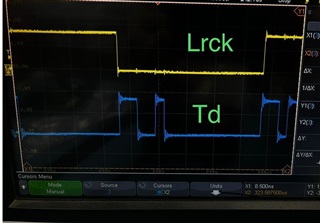
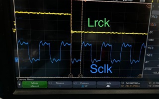
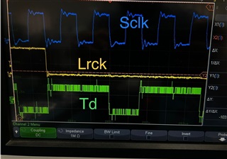
The audio output is not generating even though we are able to generate all I2S clks with following frequencies and proper clock ratios..

Sampling Rate: 48 KHz
Internal SSC MCLK for Generating TK & TF: 150000000
MCLK: 12.28 MHz 
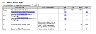
Bit CLK (TK): 1.53 MHz
Word CLK (TF): 48.00 KHz
Data (TD): data - 16 Bit 
Bit CLK to word CLK Ratio: 32 (even we tried with 64)

We observed that bit 'CLKE' is getting set in Fault register (0x08, value: 0x08) indicating the 'non-latching intermittent clock error'.
We also observed that the fault pin pulsing continuously (low for 10us with every 350us gap).
After power on and reading fault register we tied toggle the SPK_SD pin and tied tied this to SPK_FAULT pin, but even this doesn't help.

Please let us know whether this error (CLKE bit set) is generating for improper clock ratios or any distortion/delays in the clocks.

The snapshot of the schematics section of amplifier is attached for your reference. Also attached few of the i2s clock/data waveforms.

Regards,
Imran,
mJm Technologies, Bangalo
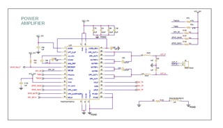
    re

  • Hello Imran,

    I see that you added an Inductor between digital ground and power ground.  The suggested layout in the datasheet shows the digital ground and power ground connected to the same ground plane.  Please short the inductor and see if you have the same issue.

    Otherwise, you need to make sure the clocks are in the exact ratios or you will get a clock error..

    Regards,
    Gregg Scott

  • Hi Gregg Scott,

    Thanks for your quick response.

    We have tried shorting the inductor between the grounds that you have mentioned, but still the no improvement.

    The CLKE bit is high in register 0x08 and the SPK_SD pin is pulsing low for 10us and 350us.

    All the three clk ratios are also proper as mentioned above. what is the tolerance b/w them?

    Is there a delay required b/w the bit CLK and the data or word clk and the bit clk. I have attached the wave forms in the previous message.

    Request you to please look into it and see are we missing any settings or any hardware problem.

    We are badly struck and the CLKE bit error is persistent.

    Regards,

    Imran

  • Imran,

    I cannot see anything incorrect in your schematic.  I assume you are able to set up the registers with I2C.  

    The only way for the CLKE to have a pulsing problem is for the clock ratios to be drifting so that the timing is off.  You could use the oscilloscope to trigger on the SPK_SD pin and also measure the MCLK to LRCLK ratio and also the SCLK to LRCLK ratio.  These could be drifting a bit.  Another issue is that the clocks might be missing for a cycle or two and they cause the CLKE to be set.

    Regards,
    Gregg Scott

  • Hi Gregg Scott,

    Thanks for your reply.

    Yes, we are configuring required settings with I2C registers.

    We have seen all the ratios are correct. 

    MCLK (12.288 MHz) to LRCLK (48KHz) ratio is 256 and

    SCLK (1.536 MHz) to LRCLK ratio is 32

    data width is 16-bits and frame width is 2.

    There is a little deviation in the above frequencies, varying within this range...

    MCLK (12.00 to 12.3 MHz)
    LRCLK (47.98 to 48.02 KHz)
    SCLK (1.528 to 1.538 MHz)

    One thing I need to bring to your attention is TAS5720A datasheet mentions about  tRise, tHLD and tSU which is about 15ns minimum.

    And our controller is ATSAMV70 which is not giving the option to set these timing delays. The SCLK to LRCK and SDIN is at the same edges without delays. Also the data and LRCK are changing on falling edge wrt SCLK.

    Please refer the snapshots of wave forms.

    Also the clks and data are continuous and there is no missing in between.

    Please suggest if anything need correction or settings..

    Regards,

    Imran

  • Imran,

    I have consulted other coworkers and will reply soon.

    Regards,
    Gregg Scott

  • Imran,

    After consulting some coworkers, the 15ns is needed to guarantee that a CLKE is not shown.  Due to variations and jitter, we need to have some buffer.  You could add some delay to the BCLK and LRCLK by adding 10pF to ground on these pins.  It would be best to control this in your DSP.

    Regards,
    Gregg Scott

  • Hi Gregg Scott,

    Thanks for your reply.

    As mentioned in my previous email, the controller we are using ATSAMV70 is not allowing to introduce setup & hold time delays in the clk signals.

    We have added the said capacitors in LRCK but it didn't help. We will also add it in other signal and try.

    Please suggest if any other thing we can try.

    Regards,

    Imran

  • I was waiting for your reply on trying the other signal.  Actually, you should add the cap to both SCLK and LRCLK (FSYNC).  I so not have any other suggestions at the moment.

    Regards,
    Gregg Scott

  • Hi Gregg Scott,

    Thanks for your reply.

    Sorry for delayed response as we were trying other options.

    As I mentioned earlier we have tried the capacitor with both the signals, but there is no improvement and there is not such delay being introduced with capacitors.

    Do you confirm that this 15ns is a must b/w the signal as per datasheet? and which our controller is not having options to introduce such delays.

    Thanks for your support.

    Regards,

    Imran

  • Imran,

    The 15ns is a minimum spec in the datasheet and it needs to be followed.  

    Regards,
    Gregg Scott