This thread has been locked.

If you have a related question, please click the "Ask a related question" button in the top right corner. The newly created question will be automatically linked to this question.

TLV320ADC5140: Line level input buffer to maximize performance (summing) and channel separation

Part Number: TLV320ADC5140
Other Parts Discussed in Thread: LMP7731, OPA1632, LM4562,

We currently utilize a Cirrus Logic ADC (stereo, I2S master) in our main product but were researching alternatives; our plan was originally to switch to ESS but we've changed our mind.  So, as this was the only chip in our design that wasn't TI, we figured we would explore the TI audio ADC lineup and have a 100% TI design.

Our device input is single-ended (basically consumer line level audio) to differential input buffer based on the OPA1632 (almost exactly like OPA1632 datasheet, page 18) except with two independently buffered Vref via LMP7731 (one per channel).  Our input buffer power supply is +/- 10V.

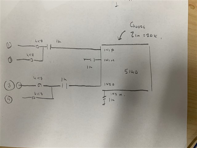
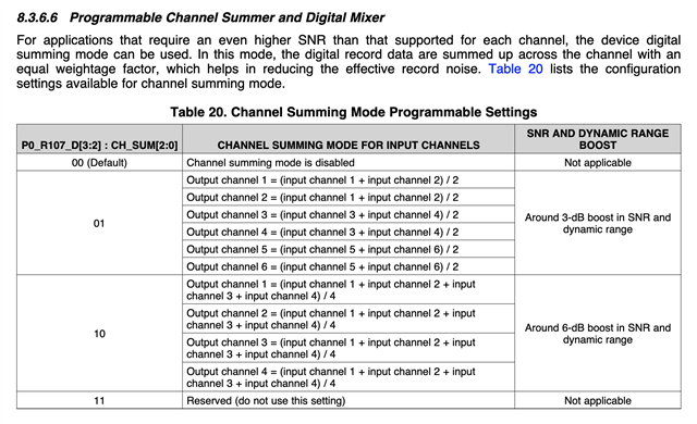
We are hoping to migrate to the LM4562 (for availability reasons) on our input buffer but we're not sure if buffering is even required on this ADC to realize the specified noise / distortion performance.  In addition to this, we are wondering if you can give us a schematic (as a starting point) to take advantage of summing the 4 inputs into 2 (stereo) however on page 35 of the TLV320ADC5140 datasheet (8.3.6.6 Programmable Channel Summer and Digital Mixer) we can't determine how to interface our input buffer to the analog input pins.  We should be able to figure out I2C from there.

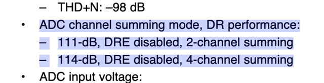
Our goal is simply to achieve the specified noise and distortion performance and maximize stereo separation (at any cost).  Any suggestions from the TI engineering team would be very appreciated.

Our current dbFS is: 18dBu, ~15.78dBV, ~17.4Vpp, ~6.15Vrms. 

Thank you!

  • Hi,

    Please wait 12-24 hours for our audio expert to comment.

    Thank you for your patience

  • If you like to combine 4 analog inputs into 2 stereo channels using Hardware then the circuit below should work.

    Choose the Input impedance of 20k.

  • TLV320ADC5140 datasheet (8.3.6.6 Programmable Channel Summer and Digital Mixer) <-- Sorry if I was unclear.  I am asking how to achieve this with our 2ch single ended input.  Please see the datasheet.   It's unclear how we can combine the 4 ADC inputs (IN1 summing with IN2 into I2S channel 1 LEFT and IN3 summing with IN4 into I2S channel 2 RIGHT) in order to realize an additional -3dB of DR.  Is this possible utilizing all 4 ADC inputs for our 2 channels?  Both in a schematic and in programming.  Table 20 is unclear to us here.  Also, your schematic is not utilizing IN3/IN4.

    For instance, the AKM AK5554VN supports "4 into 2" mode

    In e2e, Collin Wells says here regarding the xxx6140 https://e2e.ti.com/support/audio-group/audio/f/audio-forum/976615/tlv320adc5140-audio-adc-performance-clarification/3607394#3607394 "The device supports two-channel summing mode which will increase the dynamic range to 116dB" can't the TLV320ADC5140 do this to get to 111dB from 108dB?

    From the top of the datasheet:

    In addition, all of the examples are for microphone recording.  Does this mean we don't need to buffer line level input?  Do you have any example of a line level input buffer?  Is this not required on this series of ADC?

  • Shall take a look and reply in a few hours

  • As far as I recall Consumer Line inputs support 0.3vrms driving 10k. please correct me if I am mistaken. I proceed ahead with this assumption.

    I think you would need to take 1 channel of the stereo input and give it to 2 ADC Channels to realize 3db SNR improvement. The left can be given to input 1 and input 2 .P0 R107 D3.2 can be 01 . Output channel 1 would then have 3db improvement as the digital Left channel.

    Similarly The Right can be given to input 3 and input 4 .P0 R107 D3.2 can be 01 . Output channel 3 would then have 3db improvement as the Digital right Channel.

    On Page 8 of the Datasheet, we see that for a Single ended input supports 1vrms for

    Full scale value.(Refer to image below).

    To make the 0.316vrms give full scale  we can put a gain of 3 in the chip so that 1vrms is presented to the ADC.

    Page 0 register 61 can be used to setup a value of 9db gain in the chip


    You can  combine input 1,2 and input 3,4 as below.

    Since the Effective input impedance each line input should see is 10 k, we can internally set a 20k Input impedance setting in the chip. This would make an effective input impedance of 10k when 2 channels are combined together.

    Page 0 Register 60,65,70,75 can be used to set Zin of 20k.

  • Hi Sanjay, Thank you for your help. 

    Do you have any feedback about this input buffer?  Your suggestion was very simple but can we gain anything with this?  Or does the TLV320ADC5140 not require it to achieve datasheet noise and THD performance?

  • My personal  opinion is that you should be able to go in to the ADC without the Buffer. Most customers just connect the Mic outputs to the ADC input directly.