This thread has been locked.

If you have a related question, please click the "Ask a related question" button in the top right corner. The newly created question will be automatically linked to this question.

TAS2781: How to download all resister as the binary data format

Part Number: TAS2781
Other Parts Discussed in Thread: TAS2563

Hi, TAS2781 support team

When TAS2781 is used in the real system, I need the binary file(*.bin) of all resister. But the binary file can not be generated using PPC3 GUI Tool. But it looks like to be able to program the binary file using Binary Version in Menu. 

How to generate the binary file after configuring all register in PPC GUI Tool?

Thanks

Tamio

  • Hi Tamio,

    The bin file is indeed generated using PPC3, once you have all your tuning configuration you should select the "End System Integration" tile from the Home panel and follow the process flow to dump the binary along with other configuration files.
    Please let us know if you have any further questions after trying this.

    Best regards,
    -Ivan Salazar
    Applications Engineer

  • Hi, Ivan,

    Thank you for your advice.

    I can generate the binary file.

    I have more question as follows.

    1. What is the memory type for the register of TAS2781? Is it NVM? I would like to know if I need to program the binary data to TAS2781 every power-up.
    2. Are there any documents like the flowchart for programming the binary data? Or is there the sample code?
    3. Do I need to reboot to reflect the updated register? If YES, what is the method?
    4. How do I check if the binary data was programmed to TAS2781 correctly?  Do I need to compare between the original binary data and the register data in TAS2781?
    5. What operation will TAS2781 take if the binary data can not be programmed correctly?  

    Thanks

    Tamio

  • Hi Tamio,

    Let me follow up on your questions:

    1. TAS2781 program is stored in RAM, so you'll have to program the binary after each power-up
    2. TAS2781 driver will be added to this list: https://www.ti.com/tool/TAS2XXX-DRIVERS, you may use TAS2563 as a reference
    3. Registers are updated dynamically through SPI or I2C interface, don't have to reboot. However if you're manipulating audio processing related parameters it is recommended to set the device into software shutdown first to prevent artifacts at the output
    4. You could use the checksum available in register 0x7e
    5. There is a ROM operating mode, which is comparable to a simple Class-D amplifier with digital input. In this mode the digital core features such as EQ, speaker protection, DRC, etc, are not available

    Best regards,
    -Ivan Salazar
    Applications Engineer

  • Hi, Ivan

    I have two more question as follows.

    1. As far as I see the register map of the datasheet, there are actually some the hidden register. I think that the hidden register value depends on the ROM stored in the factory. Is there a possibility to be changed the hidden register value?

    2. When EC directly program the official specific register in operation, is it necessary for the checksum register(0x7e) to change? 

    3. If YES, when bit0 in a register is changed from 0 to 1, is the checksum value changed from the old_checksum value to the old_checksum +1b value? 

    4. The checksum value is configured by 1 byte. But there are many register. there are a possibility to be two bytes and more. How to calculate the checksum value?  

    Thanks

    Tamio

  • Hi Tamio,

    1. Hidden registers may be written as needed, based on the configuration files obtained through End System Integration. However these would not change in the data sheet description.
    2. Checksum in register 0x7e changes as I2C registers change during configuration script.
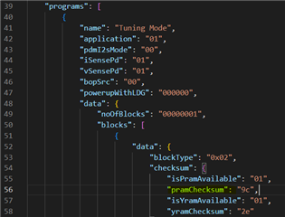
    3. Checksum value is included in the .json file which is part of the End System Integration exported files:

    Best regards,
    -Ivan Salazar
    Applications Engineer