This thread has been locked.

If you have a related question, please click the "Ask a related question" button in the top right corner. The newly created question will be automatically linked to this question.

PGA2505EVM: Unbalanced input

Part Number: PGA2505EVM
Other Parts Discussed in Thread: PGA2505

Hi Team,

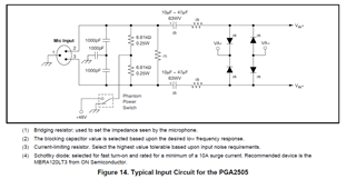
A customer is using PGA2505EVM and would like to know if it is possible to use an unbalanced audio line.

I understand from the datasheet that this device is for balanced input but I would like to know what would happen if they use an unbalanced input. Will the device work correctly (probably not). Do set the Vin- to ground work? Will the output be an unbalanced signal from Vout+? 

I hope you can help.

Regards,

Marvin

  • Hi Marvin,

    The PGA2505EVM can be used with a balanced or unbalanced audio input. However, the unbalanced input is vulnerable to common-mode noise coupling into the signal as this noise will not be rejected by the balanced architecture. Using the smallest possible length of unbalanced cable is recommended to limit noise coupling. 

    The PGA2505 is a fully differential amplifier, and therefore the output is a differential voltage between VOUT+ and VOUT-, centered around the common-mode that is set by the VCOM input pin. This is true for balanced and unbalanced inputs.

    Do set the Vin- to ground work?

    Both Vin+ and Vin- pins of the PGA2505 are DC biased at ~0.65V below the voltage set by the VCOM input pin. Connecting the Vin- pin directly to ground will violate the DC biasing of the device and produce a nonlinear response. It is highly recommended to AC couple the Vin+ and Vin- inputs. A ground(0V) input signal that is AC coupled to Vin- is a valid input as this does not affect the DC biasing of the amplifier.

    On the PGA2505EVM, if you are using the J1 microphone input connector for your signal source, the Vin+ and Vin- input pins are already AC coupled by capacitors C19 and C20. An unbalanced input such as a TR cable should be compatible with the balanced J1 input connector as this will apply the signal at pin 2 (Tip) and and ground at pins 1 and 3 (ring and sleeve). I would recommend verifying these connections before powering on the EVM as they may differ depending on your input source and cable connections.

    Regards,

    Zach

  • Hi Zach,

    The customer is working with a PGA2505DB and trying to make a similar pre-amp for unbalance audio. If they were to AC couple Vin- by connecting the ground to pins 1 and 3 on input J1, should they need all of the components in that line, or just need C20 and R6? If the input is an unbalanced source to Vin+ and ground to Vin-, will the output also be unbalanced at Vout+ and ground at Vout-?

  • Hi Marvin,

    Figure 14 below shows a typical microphone input circuit for the PGA2505. The footnotes describe the purpose of some of these components.

    For the PGA2505EVM, many of the input components shown on the schematic are not populated or are replaced with wire shunts. These are simply there to allow the user to easily configure the circuit for their application, such as adding pads or filters before the PGA inputs. Refer to figure 14 above for a simplified input structure that provides the necessary AC coupling capacitors, current limiting resistors, overvoltage protection diodes.

    The output of the PGA2505 fully differential amplifier is a differential voltage between VOUT+ and VOUT-. Differential audio signals perform best when using balanced connections and balanced interfacing is recommended for the signal chain at the output of the PGA2505.

    Regards,

    Zach

  • Hi Zach,

    Thanks for the help. One final question - -If the customer is using a pre-polarized microphone should they still need the circuit shown in figure 14?

    Regards,

    Marvin

  • Hi Marvin,

    Zach is out so I'll jump in; I'm not an expert on exactly what the term "pre-polarized microphones" but some quick reading suggests that it eliminates the need for high bias voltage requirements on some microphone types (assume like an electret-style microphone). Do you have a data sheet for the microphone element, and we can give more detail?

    If the question is more around whether or not it needs a bias supply, the circuit above can work with or without the phantom power, which is typically used to bias a FET-type output stage that is built into to many condenser-type microphones.  This is opposed to a dynamic microphone, that uses a magnetic-coupled element with a transformer output for impedance translation.  The former needs a bias supply (i.e. phantom power), the latter does not (no phantom power).

    Let me know your questions on this.

    Regards,
    Mike