Other Parts Discussed in Thread: TAS5805
Hello,
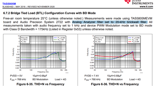
we are using the TAS5805M to output sine waves at frequencies up to 20 kHz.
At 1 kHz the Amplifiers output looks very smooth without much distortion.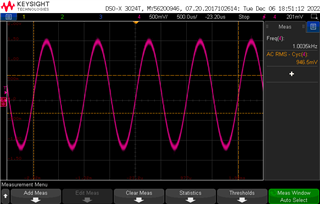
Distortions start to appear from around 3 kHz. This is the output signal at 10 kHz: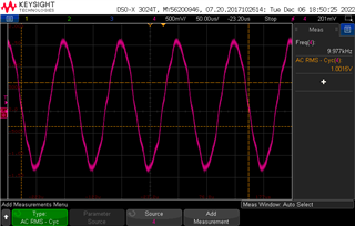
If I run the FFT, I see lots of harmonics.
Is this an expected behavior? I am using a 10 Ohms resistor on the output. The filter has a 10 uH inductor and 2x330nF = 660 nF capacitor.
I2S sends the sine values at 48 kHz sample rate. Amplifier is supplied by 12 V. 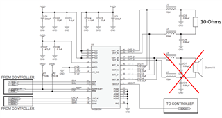
My I2C init sequence is very simple. I do not use any signal processing.
Switching frequency is set to 768 kHz.
uint8_t initSequence[][2] = {
{ 0x00, 0x00 }, // Change page to page 0
{ 0x7f, 0x00 }, // Change book to book 0
{ 0x03, 0x02 }, // HIZ
{ 0x01, 0x11 }, // Reset registers
{ 0x03, 0x02 }, // HIZ
{ CFG_META_DELAY, 5 },
{ 0x03, 0x00 }, // Sleep
{ 0x46, 0x11 },
{ 0x03, 0x02 }, // HIZ
{ 0x61, 0x0b }, // ADR as FaultZ Output
{ 0x60, 0x01 }, // ADR pin as output
{ 0x7d, 0x11 },
{ 0x7e, 0xff },
{ 0x00, 0x01 }, // Change page to page 1
{ 0x51, 0x05 },
//Register Tuning
{ 0x00, 0x00 }, // Change page to page 0
{ 0x7f, 0x00 }, // Change book to book 0
{ 0x02, 0x00 }, // fsw = 768 kHz
{ 0x30, 0x00 }, // SDOUT outputs DSP output
{ 0x4c, 0x30 }, // Digital Volume: 0 dB (default)
{ 0x53, 0x03 }, // ANA bandwidth = 175 kHz
{ 0x54, 0x00 }, // Ana gain = 0 dB
{ 0x03, 0x03 }, // PLAY
{ 0x78, 0x80 }, // Clear analog faults
};
Best regards,
Johannes Nadler