This thread has been locked.

If you have a related question, please click the "Ask a related question" button in the top right corner. The newly created question will be automatically linked to this question.

TLV320AIC3104: MIC2R data collection issue

Part Number: TLV320AIC3104

hi team:

 My customer reporting the MIC2R(pin16) can not collect the audio signal, meanwhile the PIN14 of MIC2L is workable ,here is my primary checking list with my customer ,can you help to take a look and give your professional comments? tks in advance! 

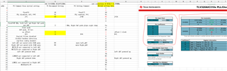
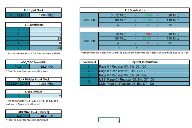
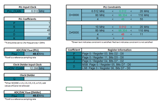
 here attached the register file ,you may check the MIC2R page for your reference.

 11-25 AIC3104 config list.xlsx

 here attached my understanding corresponding to the register list.


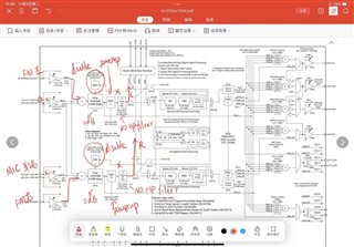
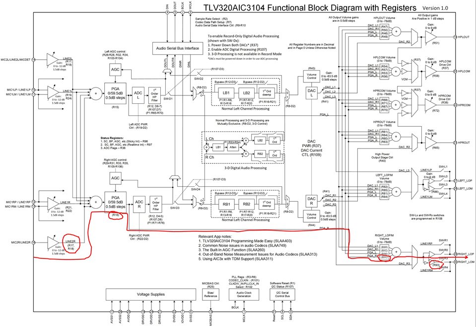
 here attached the customer system block diagram:


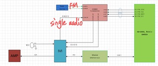
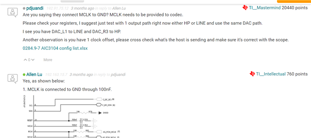
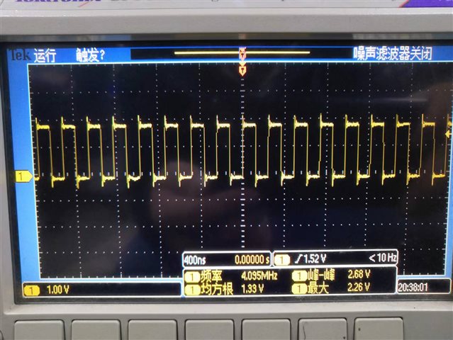
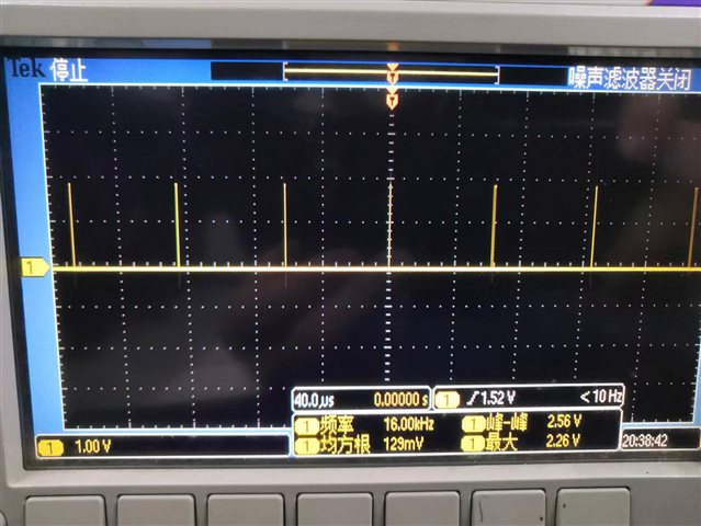
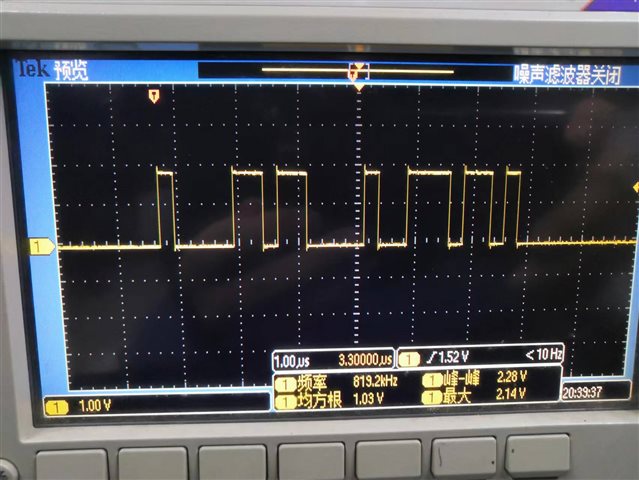
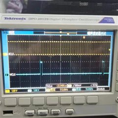
 here also attached another hardware test from the customer side:

 -> The audio source comes from 3.5mm headphone to PIN16 and 14.

There are three connection methods:

1. Normally ,audio R to PIN16 and L to PIN14.

2. Swap left and right and L to PIN16 and R to PIN14.

3. Both of the above two results ensure that there is an audio signal entering PIN16, but neither can have stereo output。(R audio missing)

->Impedance measurement test:

 1.use the multimeter diode channel(red pen to ground, black pen to chip pin) measurement results: PIN16 is 0.440, PIN14 is 0.463;

 2.use the multimeter resistance channel(red pen to chip pin , black pen to ground) measurement results: PIN16 is 6.6M, PIN14 test is 6.6M;

according the above test, i think the hardware part is okay, can you help to comment? tks !

  • Hi,

    Register 17 and 18 are the settings for MIC2L and MIC2R to left and right ADC and I see the new settings are correct 0x0F and 0xF0.

    This should be straight forward, configure the input and power up ADC.

    Are you saying you are not seeing the right channel data on the I2S_DOUT? Are you seeing the issue on different device?

    Maybe contact issue on pin 16 at device side.

    If you do the bypass mode (analog to analog) by sending MIC2R directly to one of the analog output do you have the output?

  • Hi Pdjuandi:

     tks for your comments. and you are correct. it seems like we are not seeing the right channel data on the I2S_DOUT.

     we can confirm that all the device have this same issue too. would you also help to provide a modification base on the config file to set the bypass mode?

  • You can use the block diagram that you showed above, I have highlighted the path and the registers to set as shown below.

    Regards.

  • Hi Pdjuandi:

     Tks for your comments.

     just set the register as you said for bypass mode, including PGAL and PGAR , the left lom/p and right lom/p can come with audio.

     So i think the issue of the path is ADC R + HP filter , but i check the register is okay for power up. if there any tests we can try?

     tks !

  • Your digital configuration shows the ADC sampling is 16KHz. DSP mode, slave mode with 16 bits data, but the BCLK is 4.096MHz. This is not correct.

    What sampling they want to run with? If 16KHz then BCLK should be 16KHz x 16 bit depth/channel x 2 channels which is equal 512KHz.

    Then they need to check the PLL divider if BCLK changed from 4.096MHz to 512KHz.

    See section 10.3.2.4 for DSP mode in slave mode. 

    2055.11-25 AIC3104 config list.xlsx

  • Hi Pdjuandi:

     the customer is using ADC sampling as 16KHz in DSP mode.  according to the setting of BCLK 4.096MHz, i just follow the previous setting you send.

    https://e2e.ti.com/support/audio-group/audio/f/audio-forum/1126477/tlv320aic3104-right_lop-lom-output-issue/4187692#4187692 

    so can you help you share a update config file to support? the PLL setting is still not familiar to us now.. 

     tks  again!

  • Hi Pdjuandi:

     Just check with the spec from spec and your comments before.

     my customer modify  the register as below yellow mark to set the PLL correctly, but it seems like doesn`t work.


  • Hi Allen,

    FYI, Peter is out of office for a few days so there will be a delay in response, please check back on Thursday.

    Brian

  • Hi,

    Please provide your scope capture of WCLK, BCLK and the new register settings.

    Your WCLK should be 16KHz and BCLK 512KHz.

    Regards.

  • hi 

     i try to deep dive the register and PLL setting. here attached my calculator process: 


    Base on the above PLL tree:

     i think the calculator tool also show the correct setting.

    here attached the waveform of BCLK:

    here attached the waveform of WCLK:

    here attached the waveform of DOUT:

    So i think the confusion is about the relationship of the WCLK and BCLK.

    `base on the above relationship, so BCLK=N(16)*2(left and right channels)*WCLK? Am i correct?

    but just curious, the PLL will cause the right channel not working properly?

    Another topic want to confirm it that , Qualcomm FAE said they may be related to the slots config,

    Can you share how to use this code under DSP mode?

     tks again.

  • Hi,

    The codec is in slave mode and receiving the clocks, so since BCLK is 256Fs (256x16KHz=4.096MHz) and data length is 16 the 2nd channel is empty.

    Can they try setting BCLK to 512KHz (16x2x16KHz)? 

    Regards.

  • hi ,

     here is the modification waveform with 16khz  WCLK and 512KHZ BCLK. But the right channel still no sound output. can you help to check again? tks!

     here attached the update register in mic2r chapter.

    12-12 BU AIC3104 config list.xlsx

    and also i got confusion of the  ADC fsref pll and ADC fsref divider, does the ADC fsref divider= WCLK= ADC sampling rate? So the Q should set as 6 ?

  • Hi,

    The clock and ADC configuration looks correct. The input MIC2L goes to Left ADC and MIC2R goes to the right ADC.

    Have you check the MIC2R itself is present and capture DOUT on scope as well?

    Also try changing offset to 0 cycle. These settings should work, are you connecting them right to the host and not by any chance swapped?

    If you use PLL then use PLL fsref setting otherwise the divider if PLL is not used.

    Regards.