Hi Team,
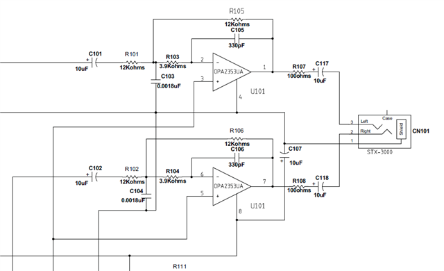
What's the purpose of the OP amp circuit on the PCM2906CEVM-U?

Thanks!
Roy
This thread has been locked.
If you have a related question, please click the "Ask a related question" button in the top right corner. The newly created question will be automatically linked to this question.
Hi Team,
What's the purpose of the OP amp circuit on the PCM2906CEVM-U?

Thanks!
Roy
The op-amp circuit serves as a LPF for analog input and output (CH1/2)
Hi Team
I have other questions as follows:
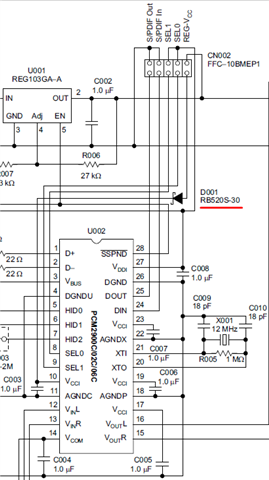
1. What is the function of D001? To prevent current reflow from Vcc1 or other reasons?
2. Can we remove the D001?

3. Can we change capacitor form electrolytic capacitor to MLCC for the design?
Does this change cause design concerns?
Thank you.
Darren
Hi,
I am out of office today for US holiday so please be patient as responses may be delayed.
Thank you for your patience.
Regards,
Hi,
1. When power supplies turn off, the diode discharges the capacitor, so it's empty when power supplies turn on again the next time.
2. I recommend following circuit connection shown if using LDO or EVM for better performace. However, a diode isn't needed for circuit design, note typical configuration 1&2 in datasheet
3. The capacitor shown in the diagram is by default a 10uF electrolytic cap, not shown on EVM user guide but shown in figure 36/37 of d/s.
Hi,
Here are some more questions :
1. For the typical configuration 1&2 in datasheet, I note the difference is using external or internal voltage regulator, will this affect performance?
2. Why should C003 be discharged at the next power-on if using LDO or EVM for better performace?
3.Why use electrolytic cap for input & output of amplifier? Does this mean that the electrolytic capacitor has a better filtering function than MLCC?
Hi Darren,
1. Noted under the image in datasheet it mentions that with REG103xA absent the analog performance of the ADC may be degraded.
2. The diode is likely used to prevent reverse current flow, discharge the capacitor so it improves noise and transient response, or both. These are likely when tying a diode to Vout of an LDO/regulator.
More information can be found in this tech blog: https://e2e.ti.com/blogs_/b/powerhouse/posts/ldo-basics-preventing-reverse-current-in-ldos
3. The design team using an electrolytic capacitor is likely for lower ESR and to prevent damage to IC. We recommend following the application outlined