This thread has been locked.

If you have a related question, please click the "Ask a related question" button in the top right corner. The newly created question will be automatically linked to this question.

TPA3255: TPA3255ampBoard-question

Part Number: TPA3255

Hi team,

My customer needs assistance.

Dear Customer Support,

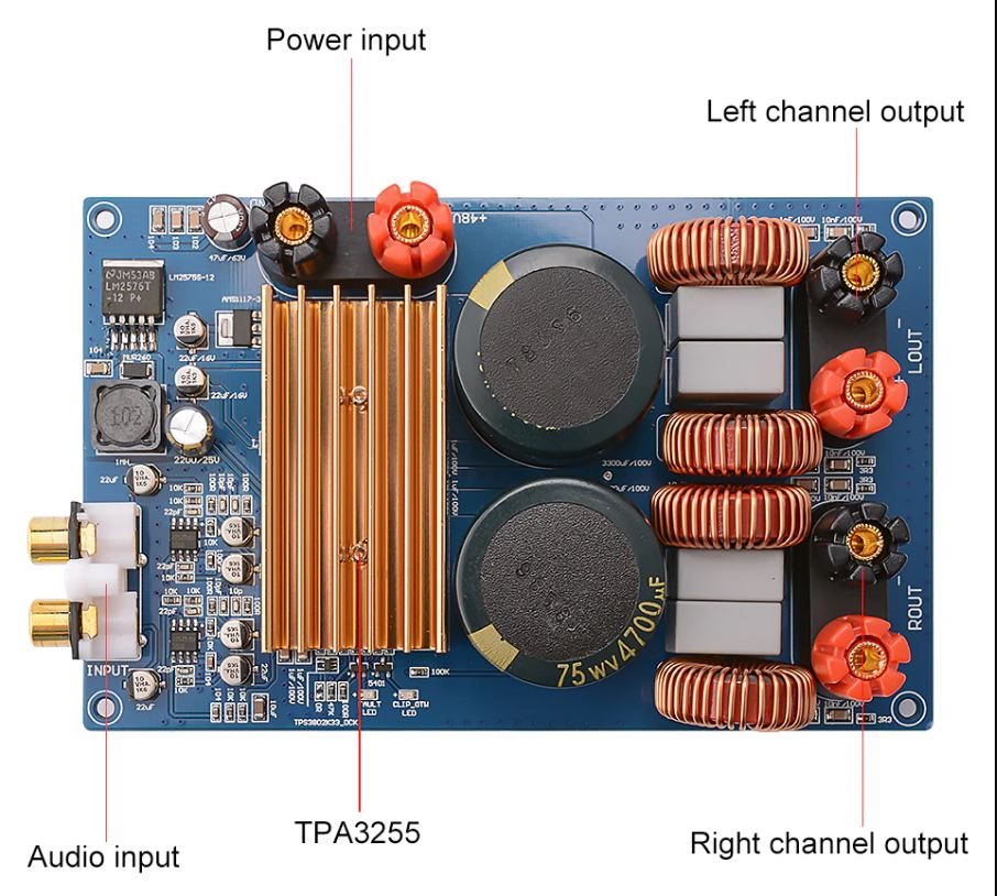
I own the TPA3255 amplifier board from Ayima (a Chinease manufacturer; the board purchased on AliExpress). Overall I quite like it. But despite this, 'just to be sure', I decided to tweak it by replacing the two input power 4700 mkF 75V electrolytic capacitors, which were installed on my board by default, with the two 70V 10000 mkF ones. But the moment I switched on the power after the replacement, the chip burned out.
The amp. board was powered with a 48V 7A Switching Power Supply unit turned up to 50 volts and had worked quite well in this mode with the board before the caps replacement.
I can add that the mentioned 48V-7A switching power supply unit remained quite alive and well in the result of the incident -- just the chip burned out.
I already bought the new TPA3255 chip for resoldering and can easily restore the original 4700 mkF caps to the board, but I would like to know the true reason behind the failure: is it something conceptual/fundamental (i.e. like 20k mkF bulk capacitance is detrimental to this design), or is it a mismath of such a huge capacitance onboard with the 48V 7A switching power, or is it just a soldering blunder that can easily be corrected, or something else?
---
Question in general: should the TPA3255 chip sustain a 20000mkF bulk capacitance when powered with 50 volts from a 48V 7A switching power supply or is it too much for it?

I'm looking forward to receiving any clue from you on this issue.

Kind regards,
Alexander,
Ukraine

  • Hi Alexander

    thank you for your question.

    let me clear some thing about your question.

    before: 4700 mkF 75V electrolytic capacitors + 48V 7A Switching Power Supply unit turned up to 50 volts -> work normally

    after: 70V 10000 mkF capactiors + 48V 7A Switching Power Supply unit turned up to 50 volts  -> chip burn out. 

    your question: you want to take a try a more larger capacitor 20000mkF capacitor and want to know is it ok or not?

    can you provide your 3 types capacitor's datasheet, then we can check what might be the reason.

    thanks

    jesse

  • Dear Jesse,
    Thank you for yor message.
    Let me answer your question.
    Before: 2*4700 mkF 75V Samwha electrolytic capacitors (as can be seen on the photo) + 48V 7A Switching Power Supply unit turned up to 50 volts -> worked normally.
    After: 2*10000 mkF 63V JB JNC Series electrolytic capacitors + 48V 7A Switching Power Supply unit turned up to 50 volts -> 1) chip instantly burned out; 2) the Power Supply unit is OK.
    I would like to know the possible reason of the chip’s burn – is it because in this configuration it can’t sustain 20k mkF bulk capacitance or is it something else?
    Datasheet for the JB's JNC series of capacitors is attached.
    Please don't hesitate to contact me should you have futher questions.

    Regards,
    Alexander

  • Hi Alexander

    it seems like no attachment.

    can you share me again.

    BTW, is that possible share use the schematic of your circuit.

    thanks.

    jesse

  • Hi Jesse,

    I am here to attach the mentioned datasheet for Alexander. Please check and help further. 

     JNC-2000H-at-85-Snap-in-Aluminum-Electrolytic-Capacitor.pdf
    If it is not available, there is a web one as well:
    https://www.jbcapacitors.com/pdf/JNC-2000H-at-85-Snap-in-Aluminum-Electrolytic-Capacitor.pdf

    Regards.

  • Hi Chong

    thank you for you information.

    i haven't seen any problem with your capacitor. it might be caused by some other issue. it is hard to say.

    can you take a try soldering another chip on the board and take a try that capacitor again?

    have you measured the output of power supply when start up the board? 

    if you don't have the chip on hand, TI.sample should be able to apply free sample.

    thanks.

    jesse

  • Hi Alexander,


    Just chiming in here I’m not a TI expert on these but have used this board and built my own versions.  These boards have capacitors that do not have a lot of voltage margin, and the heatsink they use is much smaller than the one on the TI EVM.  I personally think it’s a bad idea to run that board over 48V.  Most places that sell that board usually indicate 48V.     


    Regards,

    Jerry G

  • Hi Jesse,

    I am here to provide the repsonse from Alexander. Please check and help further. 

    Dear Jesse,

    Thank you for your attention. In response to your questions:

    1 – ‘Is that possible share use the schematic of your circuit’

    Unfortunately, I don't have the Ayima board schematic. Let's assume that it is the same as the TI's TPA3255EVM Evaluation Board (at least, there’s high probability to that): 

    https://www.ti.com/tool/TPA3255EVM 

    In exactly this schematic, is it generally possible (is it safe, to be more precise) to replace two C31 and C46 PVDD 4700 mkF 80V capacitors with the two 10000 mkF 63V JB JNC ones? Under condition that the board is powered from a 48V 7A Switching Power Supply turned up to 50V… 

    2 – ‘Can you take a try soldering another chip on the board and take a try that capacitor again?’ 

    Yes, theoretically I can solder another TPA3255 chip, but I wouldn’t like to risk burning the fresh chip that without knowing the reason of the initial failure (and that’s why I’m asking your esteemed company:)). 

    3 – ‘Have you measured the output of power supply when start up the board?’ 

    No, exactly in the moment of starting up the board with the resoldered capacitors I, of course, wasn’t wise enough to measure the power supply’s output power.

    However, we have experimented with that power supply and a single 22000 mkF 63V capacitor to see will there be any parasitic short-term power surge in the output during the start-up as a result of such a large capacitance paralleled to the output. Our oscilloscope didn’t show any parasitic impulses – the 50V in the output seem to appear quite clean, without any initial unwanted voltage peaks/surges.

    Kind regards,
    Alexander

  • If the picture is correct it does not look like that board is using the high voltage version of the 2576-12 which means your exceeding ABS Max input since the HV input runs directly to the 2576-12.  This also hurts the SNR as the part puts out a lot of noise with that high of voltage in.  If it is indeed not the HV version I would personally swap that part.  Sorry for the intrusion just trying to help.

  • Hi Jerry,

    I am here to provide the repsonse from Alexander:

    Dear Jerry,

    Thank you for your notice.

    Yes, earlier, before the capacitors' replacement in question I had changed this voltage regulator to the' -HV' counterpart. That enabled me to feed 50 volts safely to the amp board from the switching power supply.

    Kind regards,
    Alexander'

  • Hi Alexander

       It's a little hard to speculate the real reason by discussing here. Technically, it should be no problem to put large capacitor at PVDD side. Most likely the damage is caused by ESD or some shortage on the PCB. Previously, if we really need to find out the possible reason, we would give this failure device to TI's local CQE, they will help to do some failure analysis like X-ray, or decap and have a close look into the device. 

      I'm sorry maybe not enough help could be provided here.