Hi,
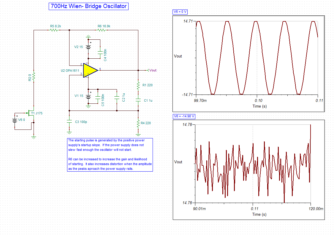
I am we got one circuit for Wien bridge Oscillator. Trying to evaluate. Created file in TINA, but not able to see 500KHz o/p.
What could be purpose of RC series switched through FET. FET is applied with 500KHz pules of 0 to -14V
Regards,
Amod
Hi,
I am we got one circuit for Wien bridge Oscillator. Trying to evaluate. Created file in TINA, but not able to see 500KHz o/p.
What could be purpose of RC series switched through FET. FET is applied with 500KHz pules of 0 to -14V
Regards,
Amod