This thread has been locked.

If you have a related question, please click the "Ask a related question" button in the top right corner. The newly created question will be automatically linked to this question.

TAS5132: THD+N cannot match specification

Part Number: TAS5132
Other Parts Discussed in Thread: TAS5086,

Hi,

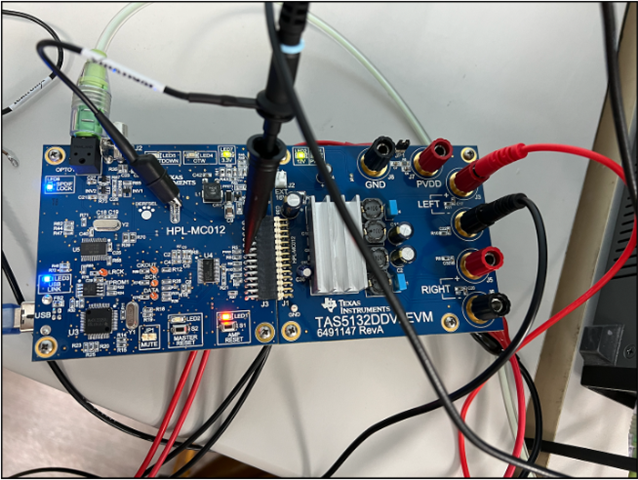
The TAS5132V2EVM board setting followed with spec sllu106a.pdf, section 3.5.

After applying the setting .cfg file TAS5132VV2EVM_BTL.cfg inside the CD

Connection to speaker can hear output result

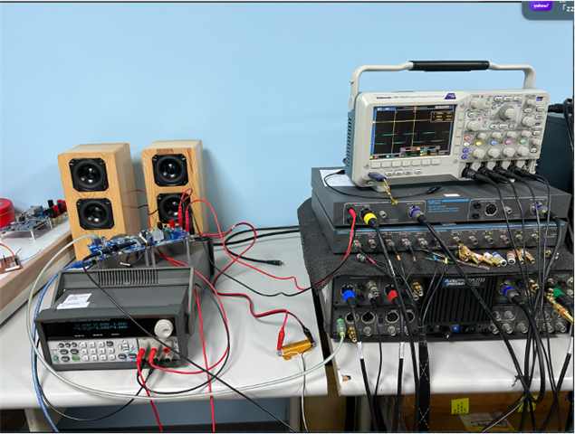
But when use AP to measure the THD+N, with 8-ohm load, the output result cannot meet sles190 spec, Figure 1 diagram at page 11.

We apply PVDD to 18V, use AP provide 1k tone as SPDIF source for TAS5086 in TAS5132V2EVM board.

Any suggestion for modification of setting or environment setup step? thanks.

  • Hi Ken

       Could you please share the test results at your side? We would like to check which area and how much difference from the datasheet plot. Usually our datasheet plot is not from EVM, we have special validation board to test these data, which board area is much larger, try to remove all the other factors outside of our device. 

  • Hello,

    We want to check the THD+N vs Output power in spec sles190 at page 11, Figure 1.

    Our test result after setting TAS5086 according to spec sllu097, section 3.5 Operational Sequence and Indicators flow is shown below:

    The diagram is measured by AP, and EVM's PVDD is set to 18V provided by Power Supply.

    Since it is totally different from the beginning. (suppose the beginning should less than 0.01%)

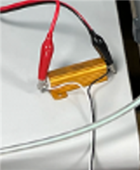
    The EVM is connect to 8-ohm load.

    The AMP reset LED turn off after use configure file inside CD, file name : TAS5132V2EVM_BTL.cfg

    Is there any suggestion about environment setting ? thanks.

  • Hi Ken

       At the input channel A of AP's Filter, may I know why the both of the input port are used? The Red and Black wire seems to connect to EVM's output directly, what is the Bal input wire used for?

      And there's additional twisted wire connected from the load, may I know where it goes? 

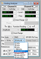
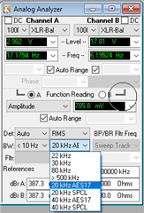
       Your waveform seems has big problems. Larger than 1% THD, is already serious distortion happens. We could firstly check in idle state, what is the noise level. Then Play a fixed frequency, do FFT analysis of the output, check what is the distortion frequency. And when you test THD, did you enabled the filter in the AP? Like below.

  • Hi Shadow,

    At the input channel A of AP's Filter, may I know why the both of the input port are used? The Red and Black wire seems to connect to EVM's output directly, what is the Bal input wire used for?

    The Bal input wire only plug on machine, which is not used during the experiment.

    And there's additional twisted wire connected from the load, may I know where it goes? 

    The twist wire is dupont line for other experiment test use, in our experiment we use alligator clips connect both ends of the 8 ohm load

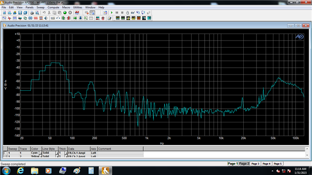
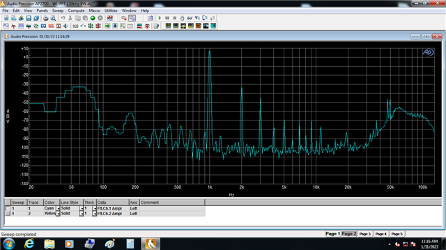
    We test the mute FFT, the result is below:


    Then we test -90dB/-60dB/-3dB FFT analyzation:

    The above diagram is -90dB FFT result, seems like mute

    The above diagram is -60dB result

    The above diagram is -3dB result, behavior seem like 0dB

    And when you test THD, did you enabled the filter in the AP? Like below.

    we apply filter setting in AP during the FFT analysis.

    Any suggestion for the TAS5132 environment setting? thanks.

  • Hi Ken

        From your waveform, seems the environment noise is too large, we need to get rid off them first before continue. From the datasheet the typical noise level from TAS5132 is between 50μV to 200μV, we need to keep the environment noise lower than this. In your waveform, at 60Hz there's -34dBV, is already 20mV. Also it's quite strange at 50KHz to 100KHz there's another peak, usually after you enabled the filter, the level will quickly drop when frequency higher than 20KHz.

       We suggest to check below things:

       1. Check the power supply, usually the low frequency noise may coming from the source. Use AP to test DC power directly, see if there's anything we could do.

       2. Remove all the unnecessary wire on the board, on the load, also on the AP. The wire could easily catch the environment noise.

       3. Enable and disable the Filter in the AP, compare the frequency sweep results, see if it really works at higher frequency. 

  • Hi Shadow,

     1. Check the power supply, usually the low frequency noise may coming from the source. Use AP to test DC power directly, see if there's anything we could do.

    I have no idea about this issue, could you provide your test setting of power supply in AP?

     2. Remove all the unnecessary wire on the board, on the load, also on the AP. The wire could easily catch the environment noise.

    The 8-ohm load's wire and measure tool's input is clean is the following test environment:

    3. Enable and disable the Filter in the AP, compare the frequency sweep results, see if it really works at higher frequency. 

    From our experiment, the setting for filter off is shown below:

    set the left window setting to none or A-weighting for filter switching off/on testing.

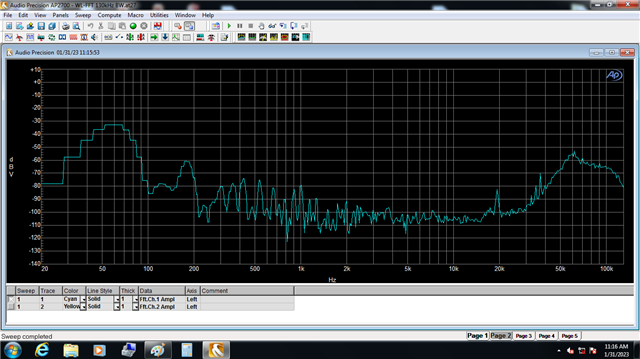
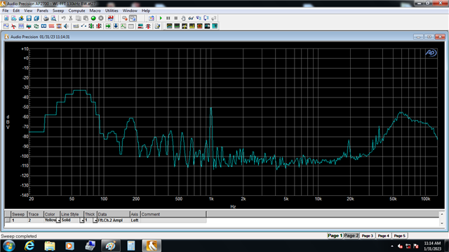
    the FFT result is shown below:

    This one is Filter setting off result

    And this one is Filter setting on result, seems nothing changed.

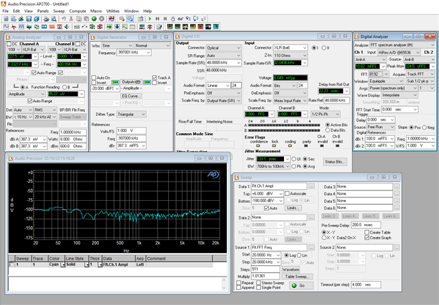
    Can you provide your test environment setting script and AP's test script files ? thanks.

  • Hi Ken

    could you provide your test setting of power supply in AP?

    Use the same FFT analysis is fine, use AP to test DC power supply directly, check the FFT results. Use oscilloscope to do the FFT is also fine.

    If choose filter didn't work, how about change the Bandwidth directly? Maybe caused by the setting of your software, how about contact your AP supplier help you with this part? 

  • Hi Shadow,

    Use the same FFT analysis is fine, use AP to test DC power supply directly, check the FFT results. Use oscilloscope to do the FFT is also fine.

    We use oscilloscope to measure power supply output FFT:


    The power supply setting is shown below:

    If choose filter didn't work, how about change the Bandwidth directly? Maybe caused by the setting of your software, how about contact your AP supplier help you with this part? 

    We test other class-D output result, seems OK for AP's measurement

    Can you provide reference TAS5132 test environment setup and test setting script? thanks.

  • Hi Ken

    I will measure the noise floor at EVM today and share to you  

  • Hi Ken

    I have measured the noise floor at TAS5828P EVM(cause I don't have TAS5123 EVM now, it doesn't matter). 

    The noise floor is shown at this picture. as your description, your noise is too high so influence the THD+N result, it seems because of your power supply is not well.