This thread has been locked.

If you have a related question, please click the "Ask a related question" button in the top right corner. The newly created question will be automatically linked to this question.

PCM3060: Synchronous Operation in Parallel Mode and Achieving the Highest SNR

Part Number: PCM3060

Setup:

The PCM3060 will operate in 3-wire parallel, single-ended output, slave mode. In parallel mode, its internal registers would assume their default values (expect the ones changed by the 3-wire setup). If this is the case, register 67 (CSEL2) would configure the DAC to operate with SCKI2, BCK2, etc.. (I2S - 2) and register 72 (CSEL1) would configure the ADC to operate with SCK1, BCK1, etc.. (I2S - 1).

My Question:

I want the PCM3060 to interface with the MCU only using a single 5-wire I2S (MCLK, BCLK, LRCLK, DIN, DOUT). To achieve this goal can I tie the SCKx, BCKx, and LRCKx pins of the PCM3060?

Follow up question:

My ultimate goal is minimizing noise. As such, will I yield a high SNR if I:

1. Tie the 2, I2S interfaces together by routing these traces under the PCM3060 and tying the 3-wire interface to their respective levels OR

2. Use SPI to configure the both the DAC and ADC to both interface with I2S-1, and tie I2S-2 to GND. 

In my previous experience with synchronous codecs, operating in parallel mode has yielded high SNR but due to the asynchronous nature of this device I am unsure what the best solution is.

  • Hi Dylan,

    I believe I understand your confusion. For clarity, digital audio input can be presented in 3-wire (MCLK or BCLK, LRCLK, DIN) or 4wire (MCLK , BCLK, LRCLK, & DIN) protocol. Note your BCLK must equal (# of channels * word length (bits) * sampling frequency).  Without an internal PLL these clocks must be synchronous meaning some multiple of each other. Noted in equation above, BCLK is a function of your sampling frequency (commonly noted as LRCLK or FSYNC).

    So, the short answer to your question is no, you can't tie SCK,BCLK,& LRCLK together because to provide valid digital audio, they must satisfy constraints outlined in datasheet and BCLK equation. 

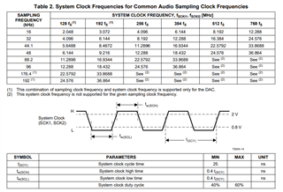
    For example, I2S audio (2 Channel data* 24-bit Word *48kHz Sampling frequency (LRCK)) --> BCLK = 2.304 MHz.(48*Fs). In slave mode, BCK must be 48Fs or 64Fs outlined in page 19 of d/s. Your SCK/MCLK depending on the device must be greater than or equal to BCK OR a common frequency supported by the codec (table 2 of d/s)

  • Hey Daveon,

    Sorry maybe I wasn't clear in my description of my question. The PCM3060 is an asynchronous codec so it is 2 separate I2S interfaces, 1 for the ADC (pins 3-6) and 1 for the DAC (pins 9-12). I mean to ask, can I tie the BCLK1 to BCLK2, LRCLK1 to LRCLK2, etc. In this way, both I2S interfaces will operate using the same output from the MCU and in synchronous mode. the other method for achieving this result would be to have the MCU communicate separately using the SPI interface and configure the PCM3060's registers which I am trying to avoid. 

    Basically I am asking how to setup this codec to operate synchronously in parallel mode. 

    Thank you for your help Slight smile

  • Hi Dylan,

    Apologies I didn't understand at first, but Yes you can provide the same clocks to both

  • Great! I'll post some of my results once I've assembled the board :) Thanks again!