This thread has been locked.

If you have a related question, please click the "Ask a related question" button in the top right corner. The newly created question will be automatically linked to this question.

TLV320AIC3254: Audible "clicking" every 1.3s in recorded files from this device

Part Number: TLV320AIC3254

Hello there,

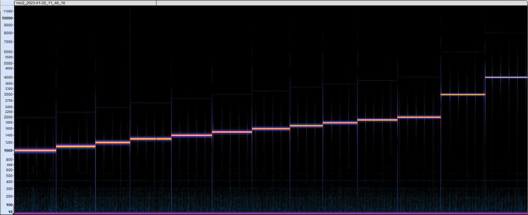
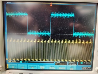
I am experiencing a peculiar issue with a TLV320AIC3254 audio codec that is interfacing with a Raspberry Pi CM4 via I2C and I2S on a carrier board of our own design.  We are recording audio from two microphones connected differentially to IN1_L/R and IN2_L/R respectively.  We have tested this unit extensively, and audio recording works reliably and well.  However, our end user complained about an audible clicking sound that occurs roughly every 1.3 seconds throughout any recording.  They did a test recording using a microphone, and a frequency generator outputting a sine wave through a speaker that swept through a range of frequencies.  To replicate this problem, we performed a similar test with an arbitrary waveform generator outputting a 100mV-amplitude sine wave directly into the codec's secondary input as a line-in signal.  During this test, I started at 1KHz, and stepped up the frequency at 100Hz intervals until I reached 2KHz; then stepped it to 3KHz and finally 4KHz.  As can be seen in the attached spectrogram, we are getting consistent clicks approximately every 1.3 seconds regardless of what frequency is used.

Oddly, in further tests, the timing of the clicks appears to be affected by the latency or block size, but only at the 44.1kHz sample rate. Normally we are running at a 48kHz sample rate, and adjusting latency or block size doesn't seem to change the timing.

Any thoughts of how to mitigate this issue would be greatly appreciated.

Thanks!


  • Hi Caleb,

    I'm having a problem seeing your spectrogram, but more importantly could you share your register maps and schematics? We need to know more about your setup before we can debug.

    Thank you,

    Jeff McPherson

  • Hi Jeff,

    Thanks for the fast response.  I reuploaded the spectrogram image on my original post, so it should bring up the larger preview when clicked.

    Here is the schematic of the audio codec.  The yellow ports represent connections to the Pi that are on a different page, but if you need those also, let me know. 

  • Hi Caleb.

    Thank you for updating the spectrogram and for the schematic. I also need a register dump from the device/whatever script you are using to configure the device to check the software side of things.

    Thank you,

    Jeff McPherson

  • REGISTER 0:
         0  1  2  3  4  5  6  7  8  9  a  b  c  d  e  f    0123456789abcdef
    00: 00 00 60 00 03 91 08 07 80 00 00 88 82 00 80 02    ..`.?????..??.??
    10: 00 08 88 82 80 01 00 04 00 00 01 00 00 01 82 00    .?????.?..?..??.
    20: 00 00 00 00 cc 66 00 00 00 00 06 00 00 00 00 00    ....?f....?.....
    30: 00 00 00 00 00 12 03 02 02 00 00 00 01 01 00 14    .....????...??.?
    40: 00 00 00 00 6f 38 00 00 00 00 00 ee 10 d8 7e e3    ....o8.....???~?
    50: 00 c0 00 00 00 00 00 00 7f 00 00 00 00 00 00 00    .?......?.......
    60: 7f 00 00 00 00 00 00 00 00 00 00 00 00 00 00 00    ?...............
    70: 00 00 00 00 00 00 00 00 00 00 00 00 00 00 00 00    ................
    80: 00 00 00 00 00 00 00 00 00 00 00 00 00 00 00 00    ................
    90: 00 00 00 00 00 00 00 00 00 00 00 00 00 00 00 00    ................
    a0: 00 00 00 00 00 00 00 00 00 00 00 00 00 00 00 00    ................
    b0: 00 00 00 00 00 00 00 00 00 00 00 00 00 00 00 00    ................
    c0: 00 00 00 00 00 00 00 00 00 00 00 00 00 00 00 00    ................
    d0: 00 00 00 00 00 00 00 00 00 00 00 00 00 00 00 00    ................
    e0: 00 00 00 00 00 00 00 00 00 00 00 00 00 00 00 00    ................
    f0: 00 00 00 00 00 00 00 00 00 00 00 00 00 00 00 00    ................
    
    REGISTER 1: 
         0  1  2  3  4  5  6  7  8  9  a  b  c  d  e  f    0123456789abcdef
    00: 01 00 01 00 00 00 00 00 00 3c 00 10 08 08 08 08    ?.?......<.?????
    10: 3f 3f 54 54 00 00 00 00 00 00 00 00 00 00 00 00    ??TT............
    20: 00 00 00 00 00 00 00 00 00 00 00 00 00 00 00 00    ................
    30: 00 00 00 68 40 00 40 01 00 40 00 5f 5f 00 03 c0    ...h@.@?.@.__.??
    40: 00 00 00 00 00 00 00 00 00 00 00 00 00 00 00 00    ................
    50: 00 00 00 00 00 00 00 00 00 00 00 00 00 00 00 00    ................
    60: 00 00 00 00 00 00 00 00 00 00 00 00 00 00 00 00    ................
    70: 00 00 00 00 00 00 00 00 00 00 00 05 00 00 00 00    ...........?....
    80: 00 00 00 00 00 00 00 00 00 00 00 00 00 00 00 00    ................
    90: 00 00 00 00 00 00 00 00 00 00 00 00 00 00 00 00    ................
    a0: 00 00 00 00 00 00 00 00 00 00 00 00 00 00 00 00    ................
    b0: 00 00 00 00 00 00 00 00 00 00 00 00 00 00 00 00    ................
    c0: 00 00 00 00 00 00 00 00 00 00 00 00 00 00 00 00    ................
    d0: 00 00 00 00 00 00 00 00 00 00 00 00 00 00 00 00    ................
    e0: 00 00 00 00 00 00 00 00 00 00 00 00 00 00 00 00    ................
    f0: 00 00 00 00 00 00 00 00 00 00 00 00 00 00 00 00    ................
    

    Hi Jeff,

    See attached.  Let me know if there's anything else I can provide.

    Thanks!

  • Hi Caleb,

    Thank you for the register map. Nothing jumps out at me as incorrect so I want to try to replicate the problem and then compare my settings to yours. Am I right that the clicking is appearing on the headphone output when using an analog input only? Is the clicking appearing on the digital audio (DOUT) or does it appear with a digital input (DIN) only?

    Thank you,

    Jeff

  • You are correct that the clicking appears when using an analog input (mic or line); however, it can be heard in a digital recording (.wav file in our case) as well as through the connected headphones.

  • Thank you for the clarification. I'll begin testing to see if I can replicate it. I apologize for asking for something else: if you have the i2c script that you use to configure your device, that will speed things up considerably.

    Thank you,

    Jeff

  • #SOFTWARE RESET
    def reset(codec):
        #select register 0
        codec.write(0x00, 0x00)
        #write 1 to reg 1 (reset value)
        codec.write(0x01, 0x01)
    
    def record48khz(codec):
        codec.write(0x00, 0x00)
        codec.write(0x05, 0x91)
        codec.write(0x0B, 0x88)
        codec.write(0x0C, 0x82)
        codec.write(0x0D, 0x00)
        codec.write(0x0E, 0x80)
        codec.write(0x12, 0x88)
        codec.write(0x13, 0x82)
        codec.write(0x1D, 0x01)
        codec.write(0x1E, 0x82)
        codec.write(0x1F, 0x00)
        codec.write(0x24, 0xEE)
        codec.write(0x25, 0x00)
        codec.write(0x2A, 0x0E)
        codec.write(0x2C, 0x00)
        codec.write(0x36, 0x03)
        codec.write(0x3F, 0x14)
        codec.write(0x51, 0xC0)
        #page 1
        codec.write(0x00, 0x01)
        codec.write(0x33, 0x68)
        codec.write(0x3E, 0x03)


    No problem.  Here's the script sent to me by our software developer.  I'm always willing to provide more information if needed.

  • Thank you for the script. I'll have an update for you by Friday, Dallas time. For record keeping purposes, please don't reply unless I haven't given you an update in a timely manner.

    Thank you,

    Jeff

  • Hi Caleb,

    A few questions. I ran your script on an EVM and noticed that the inputs had not been configured. Obviously you're getting output somehow, but is your team taking any extra steps to configure the device? I also saw your PLL settings were different than defaults, so can you tell me what clock frequencies you're using (LRCLK,BCLK,MCLK,etc.)

    Below is a sample script that gets recording (ADCs) up and running without any issues. You may have to change your clocks if possible to get it to run correctly, but it should give you some insight at the least.

    ###############################################
    # High Performance Stereo Recording
    # ---------------------------------------------
    # PowerTune mode PTM_R4 is used for high
    # performance 16-bit audio. 
    #
    # For normal USB Audio, no hardware change
    # is required.
    #
    # If using an external interface, SW2.4 and
    # SW2.5 of the USB-ModEVM must be set to
    # HI and clocks can be connected to J14 of
    # the USB-ModEVM.
    #
    # IN1L/R is routed to the LADC/RADC in a
    # single-ended manner.
    ###############################################


    ###############################################
    # Software Reset
    ###############################################
    #
    # Select Page 0
    w 30 00 00
    #
    # Initialize the device through software reset
    w 30 01 01
    #
    ###############################################


    ###############################################
    # Clock Settings
    # ---------------------------------------------
    # The codec receives: MCLK = 11.2896 MHz,
    # BLCK = 2.8224 MHz, WCLK = 44.1 kHz
    ###############################################
    #
    # Select Page 0
    w 30 00 00
    #
    # NADC = 1, MADC = 2
    w 30 12 81 82
    #
    ###############################################


    ###############################################
    # Signal Processing Settings
    ###############################################
    #
    # Select Page 0
    w 30 00 00
    #
    # Set the ADC Mode to PRB_P1
    w 30 3d 01
    #
    ###############################################


    ###############################################
    # Initialize Codec
    ###############################################
    #
    # Select Page 1
    w 30 00 01
    #
    # Disable weak AVDD in presence of external
    # AVDD supply
    w 30 01 08
    #
    # Enable Master Analog Power Control
    w 30 02 00
    #
    # Select ADC PTM_R4
    w 30 3d 00
    #
    # Set the input powerup time to 3.1ms (for ADC)
    w 30 47 32
    #
    # Set the REF charging time to 40ms
    w 30 7b 01
    #
    ###############################################


    ###############################################
    # Recording Setup
    ###############################################
    #
    # Select Page 1
    w 30 00 01
    #
    # Route IN1L to LEFT_P with 20K input impedance
    w 30 34 80
    #
    # Route Common Mode to LEFT_M with impedance of 20K
    w 30 36 80
    #
    # Route IN1R to RIGHT_P with input impedance of 20K
    w 30 37 80
    #
    # Route Common Mode to RIGHT_M with impedance of 20K
    w 30 39 80
    #
    # Unmute Left MICPGA, Gain selection of 6dB to make channel gain 0dB
    # Register of 6dB with input impedance of 20K => Channel Gain of 0dB
    w 30 3b 0c
    #
    # Unmute Right MICPGA, Gain selection of 6dB to make channel gain 0dB
    # Register of 6dB with input impedance of 20K => Channel Gain of 0dB
    w 30 3c 0c
    #
    # Select Page 0
    w 30 00 00
    #
    # Power up LADC/RADC
    w 30 51 c0
    #
    # Unmute LADC/RADC
    w 30 52 00
    #
    ###############################################
    

  • I talked to our software developer.  He's using the stock Linux driver for the 32x4 series:

    https://www.ti.com/tool/TLV320AIC32X4SW-LINUX

    The script above was his reconstruction of register values from the stock driver, but the clicking issue persists whether we attempt to use his Python script or the stock driver via ALSA Mixer.  I'm currently working with him to see if he can retrieve the exact clock settings that we're using, but if it helps, our hardware is being driven by a 12MHz crystal oscillator for the MCLK.  Does the Linux driver somehow use different PLL settings from the Windows one?  Furthermore, what crystal oscillator is used on the evaluation module?

  • Hi Caleb,

    The evaluation module doesn't have a oscillator on board. I was running it in slave mode, but it sounds like you're running the device in master mode and using the PLL to generate the other clocks. Would still like to know from your developer what the intended clock tree is supposed to look like. I'm also looping in our software team to comment on the driver question and to see if he has any comments.

  • This is good information.  Our developer can view this thread so he's in the loop.  He confirmed that our device is running in master mode with the 12MHz oscillator generating our MCLK, so ostensibly the BCLK and WCLK are set via the driver for a sample rate of <= 48000, probably from the PLL as you've indicated.  I'll follow up when I receive the info about our existing clock tree.

  • Great.  do you have any reason to believe that the driver is causing a problem or any checks the customer can do to confirm?

  • Hi Guy

    What I want to know is what the sample rate and bitclk is during 44.1kHz recording? Have the system-internal resampling worked during 44.1kHz recording?  I wonder what the latency or block size you have tried during 44.1kHz recording?

    Can you try one test? Write all the recorded data in the RAM first, after the recording, then write into file and check whether the clicks are still on? This issue seemed the write-file issue. I want to check how large buffer will be written into the file once.

    You can try another way that loopback the recorded data to the output directly, and listen and check whether the clicks are on instead of store into the file.

  • Hello,

    We did change the recording mode to 44.1kHz in a prior test, and we used a block size of 44100/4 = 11025 to act as our latency.  Sample rate was 44100, but using this setting caused us a lot of problems.  BCLK frequency is set by the driver; if our codec is in Master mode according to the diagram below and our schematic, then BCLK should be 1.536 MHz with a 48KHz WCLK.  Dividing BCLK/WCLK is 32, and multiplying 44.1K by 32 yields 1.4112MHz for the BCLK at 44.1kHz.  However, I have no idea if this is actually right.

    Currently our device is set up to write all recorded data to RAM until the time limit, at which point it writes everything to a file.

    On our existing setup, we have the codec outputting the audio through headphones.  Barring the noise from the headphone jack, the periodic clicks can still be heard this way.  It's just easier to hear and visualize them by relying on the recorded file.

    The configuration below looks exactly like how our codec is configured, only we are using a 12MHz crystal oscillator in lieu of a 24MHz.

  • Can you use the scope to measure the bck and WS clk during 44.1kHz recording?

    Kindly post the waveform, I will check them. Thanks.

  • Hello,

    Sorry for the delayed reply; I was out on vacation last week.

    Unfortunately, we weren't able to make recording work reliably at 44.1KHz, so we have been using 48KHz for that reason.  Here are the WCLK and BCLK waveforms overlaid on each other at 48KHz.  Perhaps you all have an idea of why 44.1KHz isn't working for us based on the documentation we've posted thus far?

  • Hi,

    To get the 44.1KHz sampling to work with 12MHz MCLK, please configure the PLL and divider with the value shown below:

    From the script shown above which I have added my comments below, it looks like you are setting it as slave mode and the divider is not correct giving 23.4KHz sampling and input ADC path is not configured correctly.

    #SOFTWARE RESET
    def reset(codec):
        #select register 0
        codec.write(0x00, 0x00)
        #write 1 to reg 1 (reset value)
        codec.write(0x01, 0x01)
    
    def record48khz(codec):
        codec.write(0x00, 0x00) 	- page 0
    				- Reg.4 default, PLL Input=CODEC_CLKIN=MCLK
        codec.write(0x05, 0x91) 	- PLL powered, P=R=1
    				- Reg.6 default, J=4
    				- Reg.7 & 8 default, D=0
        codec.write(0x0B, 0x88) 	- NDAC powered with NDAC=8
        codec.write(0x0C, 0x82)	- MDAC powered with MDAC=2
        codec.write(0x0D, 0x00)	- Reg.13 & 14, DOSR=128
        codec.write(0x0E, 0x80)
        codec.write(0x12, 0x88)	- NADC powered with NADC=8
        codec.write(0x13, 0x82)	- MADC powered with MADC=2
    				- Reg.20 default, AOSR=128
    				- Reg.27 default, I2S, 16 bit and slave mode
        codec.write(0x1D, 0x01)	- BDIV_CLKIN = DAC_MOD_CLK
        codec.write(0x1E, 0x82)	- BCLK N powered up with divider=2
        codec.write(0x1F, 0x00)	- 2nd ASI, WCLK2=BCLK2=ADC_WCLK=DIN2=GPIO
        codec.write(0x24, 0xEE)	- ADC Flag, all ADC paths are powred up
        codec.write(0x25, 0x00)	- DAC Flag, all DAC paths are powered down
        codec.write(0x2A, 0x0E)	- Sticky flag, overflow in left and right ADC
        codec.write(0x2C, 0x00)	- Sticky flag for Headset
        codec.write(0x36, 0x03)	- DIN as Primary Data
        codec.write(0x3F, 0x14)	- Both Left and Right DAC powered down
        codec.write(0x51, 0xC0)	- Left and Right ADC powered up
    				- Reg.82 default, Left and Right ADC muted
        #page 1
        codec.write(0x00, 0x01)	- page 1
    				- Reg.2 default, Analog block disabled, AVDD LDO powered down
    				- Reg.9-25 default, no DAC output path
        codec.write(0x33, 0x68)	- MICBIAS powered up from LDOIN = 2.5V
    				- Reg.52 default, No input connected to Left MICPGA P terminal
    				- Reg.54 default, No input connected to Left MICPGA N terminal
    				- Reg.55 default, No input connected to Right MICPGA P terminal
    				- Reg.57 default, No input connected to Right MICPGA N terminal
    				- Reg.59 default, Left MICPGA=0dB
    				- Reg.60 default, Right MICPGA=0dB
        codec.write(0x3E, 0x03)	- ADC volume flag

    Please try with the above PLL settings, configure your input path and provide the latest register dump.

    Regards.

  • Our developer has informed me that switching our entire system over to 44.1kHz will greatly complicate this troubleshooting process.  Besides the clicking issue I've described in my original post, we aren't having any problems with 48kHz, and I am afraid that this conversation is taking a very costly turn.  Therefore, please regard 48kHz recording as a requirement going forward.

    What should our PLL settings look like for 48kHz recording?

  • Here is one setting for 48KHz with 12MHz MCLK.

    Regards.

  • Hello,

    Here are the clock values from our register dump.  Our developer has informed me that our clock and PLL coefficients are identical to the chart shown.  P = 1, R = 1, J = 8, D = 1920 (there is no mention of K in the register docs).

    Page 0 / Register 4: 0x03 Clock Setting Register 1 00000011 

          0: Reserved, Write only default values 0: Low PLL Clock Range 00: Reserved, Write only default values 00: MCLK pin is input to PLL 11: PLL Clock is CODEC_CLKIN

    Page 0 / Register 5: Clock Setting Register 2, PLL P and R Values - 0x00 / 0x05 10010001

          1: PLL is powered up 001: P = 1 001: R = 1

    Page 0 / Register 6: Clock Setting Register 3, PLL J Values 00001000

          00 Reserved. Write only default values 001000: 8

    Page 0 / Register 7: Clock Setting Register 4, PLL D Values (MSB) 00000111

          00 Reserved. Write only default values 000111: 0007

    Page 0 / Register 8: Clock Setting Register 5, PLL D Values (LSB) 10000000

          7 + 8:  0000011110000000 = 1920

    Page 0 / Register 11: Clock Setting Register 6, NDAC Values 10001000

          1: NDAC divider powered up 0001000: NDAC = 8

    Page 0 / Register 12: Clock Setting Register 7, MDAC Values 10000010

          1: MDAC divider powered up 0000010: MDAC = 2

    Page 0 / Register 18: Clock Setting Register 8, NADC Values 10001000

          1: NADC divider powered up 0001000: NADC = 8

    Page 0 / Register 19: Clock Setting Register 9, MADC Values 10000010

          1: MADC divider powered up 0000010: MADC = 2

    Page 0 / Register 25: Clock Setting Register 10, Multiplexers 00000000

          0000 0 Reserved. Write only default values 000: CDIV_CLKIN= MCLK

    Page 0 / Register 26: Clock Setting Register 11, CLKOUT M divider value 00000001

          0: CLKOUT M divider powered down 000 0001: CLKOUT M divider = 1

    Page 0 / Register 30: Clock Setting Register 12, BCLK N Divider 10000010

          1: BCLK N divider powered up 0000010: BLCK N divider = 2

    Page 0 / Register 32: Audio Interface Setting Register 5 - 0x00 00000000

          0000 Reserved. Write only default values  0: Primary Bit Clock(BCLK) is used for Audio Interface and Clocking 0: Primary Word Clock(WCLK) is used for Audio Interface 0: ADC Word Clock is same as DAC Word Clock 0: DIN is used for Audio Data In

  • I tested on the EVM with 48KHz sampling then record with 44.1KHz using tone from audio precision that is swept from 1Khz to 2Khz in 100Hz step and I don't hear any click when the tone changes. See attached files.

    The above slave mode settings look okay.

    Regards.

  • Our configuration is much different from your evaluation kit.  According to the EVK schematic, MCLK is not being driven by a 12MHz crystal oscillator at all.  We're using this codec in an embedded application where MCLK is sourced by a 12MHz oscillator, because the only four I2S lines the Raspberry Pi CM4 provides are BCLK, WCLK, DIN, and DOUT.  Currently we are running this in slave mode, as we've verified that the BCLK and WCLK signals are coming from the Pi, not the codecs.  Is it technically correct to run the codec in slave mode with this configuration?

  • Hi Caleb,

    To address the K value, K is just the floating point of J.D i.e. J is the integer and D is the fractional part.

    I believe Peter tested this in slave mode according to your settings but we'll double check specifically with a 12MHz MCLK. There have been a couple changes with the PLL values that we started with and what Peter recently recommend. Can you share your developers most recent configuration script?

    Thanks,

    Jeff McPherson

  • Hi Jeff,

    Thanks for the clarification of the K value.  It seems now that our PLL and clock coefficients are setup to their defaults.

    So to reiterate, our codec is being configured by the Linux driver and we aren't changing our PLL values to anything different.  However, our developer tweaked a few register values simply to address an audible pop we were experiencing.  Even without those changes, the clicks persist.

  • As a software guy, I have a workround solution that is use software resampling from 44,1kHz to 48kHz in audio framework. The codec still works in 48kHz. In all the mobile phone and tablet projects, 48kHz is the standard setting, any other sample rates audio clips would be resampling to 48kHz in the audio framework.

    As to the issue, kindly dump the registers? 

  • Hi there,

    Here is the latest register dump.  As for the resampling, would we have to resample from 44.1kHz to 48kHz in Linux?

    Thanks!

    PAGE 0 
         0  1  2  3  4  5  6  7  8  9  a  b  c  d  e  f    0123456789abcdef
    00: 00 00 60 00 03 91 08 07 80 00 00 88 82 00 80 02    ..`.?????..??.??
    10: 00 08 88 82 80 01 00 04 00 00 01 00 00 01 82 00    .?????.?..?..??.
    20: 00 00 00 00 cc 66 00 00 00 00 00 00 00 00 00 00    ....?f..........
    30: 00 00 00 00 00 12 03 02 02 00 00 00 01 01 00 14    .....????...??.?
    40: 00 00 00 00 6f 38 00 00 00 00 00 ee 10 d8 7e e3    ....o8.....???~?
    50: 00 c0 00 00 00 00 00 00 7f 00 00 00 00 00 00 00    .?......?.......
    60: 7f 00 00 00 00 00 00 00 00 00 00 00 00 00 00 00    ?...............
    70: 00 00 00 00 00 00 00 00 00 00 00 00 00 00 00 00    ................
    80: 00 00 00 00 00 00 00 00 00 00 00 00 00 00 00 00    ................
    90: 00 00 00 00 00 00 00 00 00 00 00 00 00 00 00 00    ................
    a0: 00 00 00 00 00 00 00 00 00 00 00 00 00 00 00 00    ................
    b0: 00 00 00 00 00 00 00 00 00 00 00 00 00 00 00 00    ................
    c0: 00 00 00 00 00 00 00 00 00 00 00 00 00 00 00 00    ................
    d0: 00 00 00 00 00 00 00 00 00 00 00 00 00 00 00 00    ................
    e0: 00 00 00 00 00 00 00 00 00 00 00 00 00 00 00 00    ................
    f0: 00 00 00 00 00 00 00 00 00 00 00 00 00 00 00 00    ................
    
    PAGE 1
         0  1  2  3  4  5  6  7  8  9  a  b  c  d  e  f    0123456789abcdef
    00: 01 00 01 00 00 00 00 00 00 3c 00 10 08 08 08 08    ?.?......<.?????
    10: 3c 3c 54 54 00 00 00 00 00 00 00 00 00 00 00 00    <<TT............
    20: 00 00 00 00 00 00 00 00 00 00 00 00 00 00 00 00    ................
    30: 00 00 00 68 40 00 40 01 00 40 00 37 37 00 03 c0    ...h@.@?.@.77.??
    40: 00 00 00 00 00 00 00 00 00 00 00 00 00 00 00 00    ................
    50: 00 00 00 00 00 00 00 00 00 00 00 00 00 00 00 00    ................
    60: 00 00 00 00 00 00 00 00 00 00 00 00 00 00 00 00    ................
    70: 00 00 00 00 00 00 00 00 00 00 00 05 00 00 00 00    ...........?....
    80: 00 00 00 00 00 00 00 00 00 00 00 00 00 00 00 00    ................
    90: 00 00 00 00 00 00 00 00 00 00 00 00 00 00 00 00    ................
    a0: 00 00 00 00 00 00 00 00 00 00 00 00 00 00 00 00    ................
    b0: 00 00 00 00 00 00 00 00 00 00 00 00 00 00 00 00    ................
    c0: 00 00 00 00 00 00 00 00 00 00 00 00 00 00 00 00    ................
    d0: 00 00 00 00 00 00 00 00 00 00 00 00 00 00 00 00    ................
    e0: 00 00 00 00 00 00 00 00 00 00 00 00 00 00 00 00    ................
    f0: 00 00 00 00 00 00 00 00 00 00 00 00 00 00 00 00    ................
    

  • There're many open source resampling code. Actually,  alsa contain a resampling feature, you may as well leverage it.

    Sample as following

    linux - Alsa resampling - Unix & Linux Stack Exchange

  • So, we are confused now.  Does the driver not natively support 48kHz recording despite that the codec does?  Should we be using ALSA and the Linux driver at 44.1kHz?  As far as we know, the driver supports it, so I don't understand the push to use 44.1K.  I also fail to see how this will resolve the clicking issue, since we did previously attempt recording at 44.1kHz (bypassing all our other custom back-end using 48K) and the clicking never went away.

  • Hi Caleb,

    Driver only set the samplerate register, it won't do any resampling. Kernel mainly focus on controlling instead of data processing. If you set the register samplerate to 44.1kHz, all of the audio data must be resampling to 44.1kHz before transmitting to the chip. For example. the audio clip is 48kHz, and chip is set to 44.1kHz, kindly resample from 48kHz to 44.1kHz, before transmitting to chip.

    BR

    Shenghao Ding