Hi,
We are using tlv320aic3262 codec for our platform. We wanted to ser TLV codec as a master and I2S as slave,
We didrequired devce tree on linux kernel changes as mentioned below
sound0: sound0 {
compatible = "simple-audio-card";
simple-audio-card,name = "tlv320aic3262-hifi";
simple-audio-card,format = "i2s";
simple-audio-card,bitclock-master = <&sound_master>;
simple-audio-card,frame-master = <&sound_master>;
simple-audio-card,cpu {
sound-dai = <&i2s0>;
//dai-tdm-slot-num = <2>;
};
sound_master: simple-audio-card,codec {
sound-dai = <&tlv320aic3262>;
system-clock-frequency = <12288000>;
};
};
&i2c1 {
status = "okay";
tlv320aic3262: codec@18 {
compatible = "ti,aic3262";
reg = <0x18>;
#sound-dai-cells= <0>;
status = "okay";
};
};
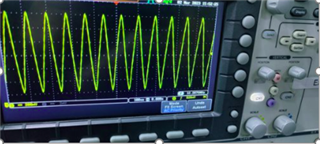
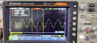
OUTPUTS:
[ 6.188897] *********** TLV Codec Master mode****************
[ 6.188900] *********** TLV Codec Right J****************
[ 6.198037] ******I2S-C Slave***** cdns_i2s_set_fmt 409 sound/soc/cadence/cadence-i2s.c
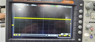
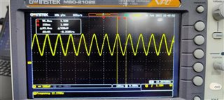
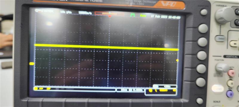
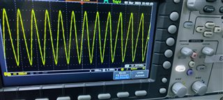
[ 6.211552] ******I2S-C I2S Normal***** cdns_i2s_set_fmt 458 sound/soc/cadence/cadence-i2s.cAfter doing this we are not able capture or playback any wav file, we are suspecting that master not able to generate the clock.
I have attached the shell script for all the codec register setting.
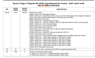
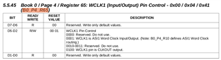
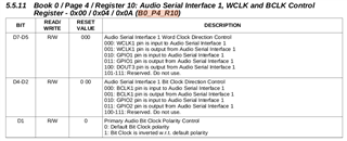
#########################################
#codec-18.sh
#########################################
#Software reset
i2cset -f -y 2 0x19 0x0 0x0
i2cset -f -y 2 0x19 0x7f 0x0
i2cset -f -y 2 0x19 0x1 0x1

#clock configuration(same for asi1 & as2)
i2cset -f -y 2 0x19 0x0 0x0
i2cset -f -y 2 0x19 0x4 0x0
i2cset -f -y 2 0x19 0xb 0x81
i2cset -f -y 2 0x19 0xc 0x82
i2cset -f -y 2 0x19 0xd 0x00
i2cset -f -y 2 0x19 0xe 0x80

i2cset -f -y 2 0x19 0x12 0x81
i2cset -f -y 2 0x19 0x13 0x82
i2cset -f -y 2 0x19 0x14 0x80

#power & analog configuration
i2cset -f -y 2 0x19 0x0 0x1
i2cset -f -y 2 0x19 0x1 0x0
i2cset -f -y 2 0x19 0x7a 0x1
i2cset -f -y 2 0x19 0x79 0x33 # ref charging time

#audio serial interface routing configuration for ASI1
i2cset -f -y 2 0x19 0x0 0x4
i2cset -f -y 2 0x19 0x1 0x00
i2cset -f -y 2 0x19 0x8 0xf0
i2cset -f -y 2 0x19 0xa 0x24 # Master mode set for B0_P4_R10

#signal processing setting
i2cset -f -y 2 0x19 0x0 0x0
i2cset -f -y 2 0x19 0x3c 0x1
i2cset -f -y 2 0x19 0x3d 0x1


#output channel configuration
i2cset -f -y 2 0x19 0x0 0x1
i2cset -f -y 2 0x19 0x3 0x0
i2cset -f -y 2 0x19 0x4 0x0
i2cset -f -y 2 0x19 0x1b 0x30

i2cset -f -y 2 0x19 0x0 0x0
i2cset -f -y 2 0x19 0x3f 0xc0

i2cset -f -y 2 0x19 0x0 0x1
i2cset -f -y 2 0x19 0x1f 0xb9
i2cset -f -y 2 0x19 0x20 0xb9

i2cset -f -y 2 0x19 0x21 0x28
i2cset -f -y 2 0x19 0x22 0x3e
i2cset -f -y 2 0x19 0x23 0x30
i2cset -f -y 2 0x19 0x1f 0x80 #
i2cset -f -y 2 0x19 0x20 0x80

i2cset -f -y 2 0x19 0x0 0x0
i2cset -f -y 2 0x19 0x40 0x40

i2cset -f -y 2 0x19 0x0 0x1
i2cset -f -y 2 0x19 0x09 0x70
i2cset -f -y 2 0x19 0x1b 0x33

i2cset -f -y 2 0x19 0x0 0x1
i2cset -f -y 2 0x19 0x09 0x10

#adc config
i2cset -f -y 2 0x19 0x0 0x1
i2cset -f -y 2 0x19 0x8 0x0
i2cset -f -y 2 0x19 0x34 0x20 #diff
i2cset -f -y 2 0x19 0x36 0x80
i2cset -f -y 2 0x19 0x37 0x20 #diff
i2cset -f -y 2 0x19 0x39 0x80
i2cset -f -y 2 0x19 0x3b 0x0c #diff
i2cset -f -y 2 0x19 0x3c 0x0c #diff
i2cset -f -y 2 0x19 0x3d 0x0

i2cset -f -y 2 0x19 0x0 0x0
i2cset -f -y 2 0x19 0x51 0xc0
i2cset -f -y 2 0x19 0x52 0x0
Thanks & BR
Rizwan Chikodi