Other Parts Discussed in Thread: PCM1808,
To whom it concerns,
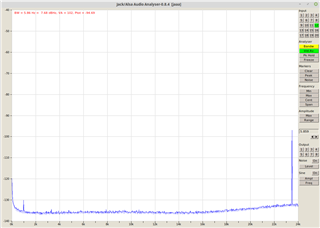
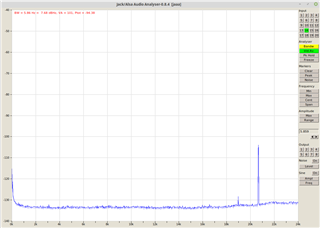
We're currently developing the second revision of a product which uses four PCM1802s to sample eight analog inputs. One acts as the master and provides bit and word clocks to the other three. The system clock is supplied by a fixed oscillator or by an optical ADAT receiver (this selection has no bearing on the noise). We've seen improvements in general for noise by changing the layout to reduce the length of the analog paths in this second revision, but as we've done that, these narrow spikes have started to become more apparent. Their range has been observed to be within 17.2-23.7kHz using 48kHz sampling; they're also present at 44.1kHz. We've attempted to remove them for a number of weeks now and have tried everything we can think of, short of making a dedicated development board.
What we've observed:
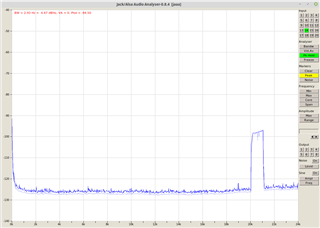
- The spikes shift based on temperature, as you can see in the peak-hold image. This is for normal board warmup, but a butane lighter was also held near an ADC and a similar effect was observed (the shift direction seems to vary).
- Other added noise or legitimate signals seem to reduce their peaks. Sidelobes can even be created by touching the audio input by just the right amount, which means some modulation is occurring. This would appear to be similar to the effects of dithering, except that the RMS value of the noise is around 100 LSbs which would rule out quantization noise directly.
- The frequencies are not consistent within a single stereo ADC, but some overlap may be present (e.g. the ~19kHz peak for input #14 on our RME Hammerfall card which is interpreting ADAT, as shown below). We would have at least expected the two channels to match.
- The peak frequencies vary with the sampling rate, but it's difficult to see a definite pattern. The individual ADCs themselves seem to be the biggest determining factor of the frequencies, but again it's hard to be sure.
- We've viewed the noise spikes now through four different FFT softwares, and all show their presence. One of those methods involved capturing a time series directly.
- An oscilloscope shows a similar data output pattern, so it doesn't seem like the ADAT transmitter (a CoolAudio V1401) is generating these spikes digitally. Other experiments pretty much rule out the two ADAT ICs (also a V1402).
What we've attempted:
- Shorting the ADC inputs to VREF1 (while disconnecting the inputs from any drivers). The frequencies tend to shift towards the Nyquist limit, but the spikes don't go away and may even become worse. In fact, on a noisy input circuit we evaluated, the spikes are only present with the inputs shorted. This again proves that other external noise is masking them.
- Adding more capacitance to VREF1 (a large 47uF electrolytic). No change. We normally use 470nF/0402 as a bypass since space is tight.
- Adding a 1kohm series resistor in line with DOUT before driving a 20-25pF capacitance. This made a positive change in some short noise spikes, but not the very tallest ones reaching around -100dBFS. This capacitance is larger than ideal but it doesn't seem to be the cause of the main spikes.
- Adding a 1kohm/0402 series resistor between VREF2 and 5V. This added other noise which wasn't present before, but didn't help the spikes. We found this somewhat unusual, but a through-hole bypass capacitor had to be used which perhaps increased inductance and/or antenna effects.
- When the above resistor broke on one end, we had to press against the capacitor to get it to contact. When the pressure is momentarily released, the VREF2 connection breaks and the spike seems to die down while "melting" towards a lower frequency. We took a short video of this effect.
- Turning on or off the DC filter bypass. No change. We would like to pass DC sometimes as this device is being used for both audio and Eurorack control signals (we were employing the PCM1808 previously). This requirement does restrict the available ADC choices.
- Attempting to terminate the system clock with an RC network. No change. Furthermore, the jittery external clock doesn't modify the spikes versus the internal clock.
- Moving both of the 3.3V and 5V capacitors (4.7uF and 0.47uF, respectively) closer to the IC. Only marginal improvements in unrelated noise were observed.
Has this effect ever been seen by TI or any customers? We can't seem to find any noise floor graphs like those we attach; all have some sort of signal applied, which of course masks this effect. This is a little bit suspicious, to be honest. We're using a 24-bit left-justified format and a 64x OSR; we can't move to 128x due to the CoolAudio ICs' lack of support for it. The PCM1802s are from JLCPCB/LCSC; we're assuming they're not counterfeit. We're not sure how to proceed at this point but may be willing to consider a different ADC. Thanks for any help you can provide.
- Arthur