This thread has been locked.

If you have a related question, please click the "Ask a related question" button in the top right corner. The newly created question will be automatically linked to this question.

PCM6480-Q1: Distortion of large low-frequency signals

Part Number: PCM6480-Q1

Hi,

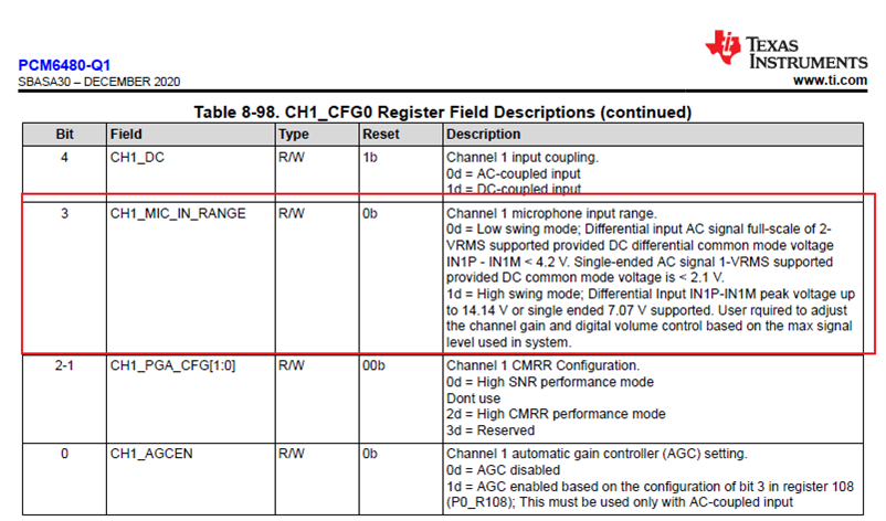
  I am using PCM6480-Q1 in High swing mode. 

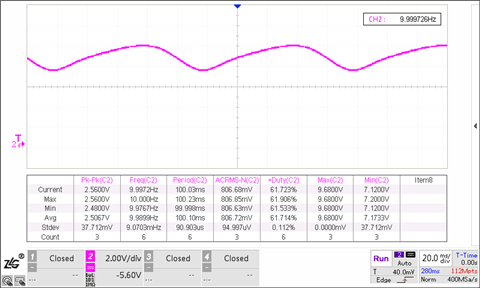
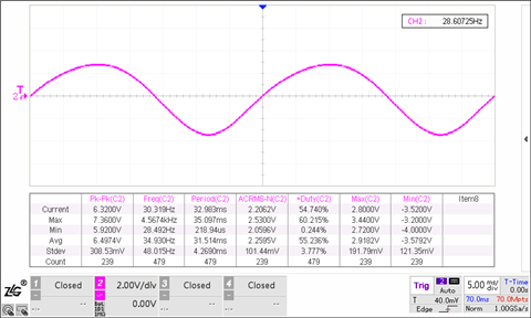
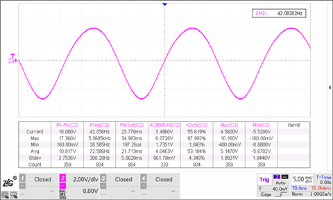
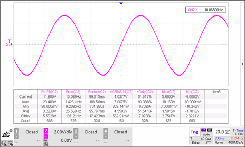
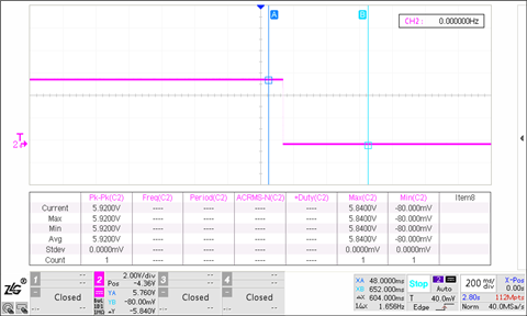
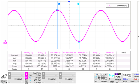
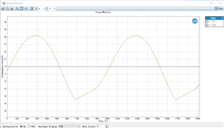
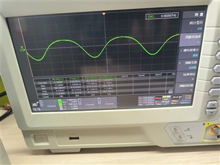
  When I give a 10Hz sine wave input, and the signal is greater than 1V rms, the lower half of the signal will be distorted after passing through the DC blocking capacitor.

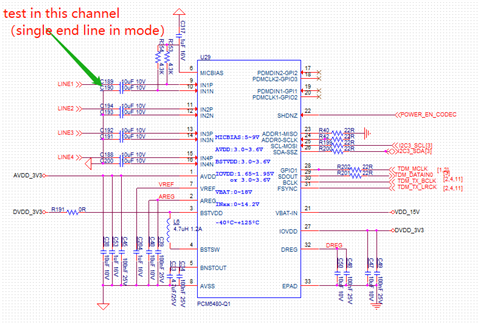
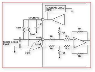
 Here is our design schematic:

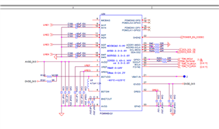
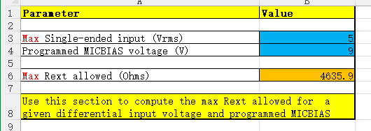
After I checked the forum, I found that the micbias needs to be set, so I added a 9V bias according to the schematic design.

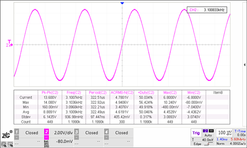
The pull-up resistor I currently use is 4.3k, and I found that the waveform is still distorted, and the form is different.

Please provide me some advice.

Thanks for your help.

  • Have you set bit CH1_MIC_IN_RANGE as 1?

    Cn you Please send me the  Waveform on the pin with oscilloscope set on DC Coupling?

    Also if the Frequency is changed to 1Khz does the waveform become OK?

  • 1. I have set MIC_IN_RANGE bit to 1 for channel 1.

    This is the register value I got using I2CTool:


    2. Here is the DC coupling mode image of the oscilloscope: (The AC effective value of the input signal is 3.2V rms)

    3. The layout we are currently using is as follows

    4. 1KHz signal is still not distorted when the input reaches 5V rms.

    5. Here is the code I used to configure the PCM6480-Q1.


        initGpio_export(CODEC_EN_PORT_NUM);

        set_GpioDirection(CODEC_EN_PORT_NUM, GPIO_OUT);

        set_gpioValue(CODEC_EN_PORT_NUM, GPIO_LOW);

        QThread::msleep(50);

        set_gpioValue(CODEC_EN_PORT_NUM, GPIO_HIGH);

        QThread::msleep(50);

        //48k 32bit I2S

        // # Already Release SHDNZ to HIGH.

        // # Wait for 1ms.

        // # Wake-up device by I2C write into P0_R2 using internal AREG

        // w 90 02 01

        i2c_writeData(0x02, 0x01);

        // # Powerdown MICBIAS and ADC channels on fault detection (overtemperature, and so forth)

        // w 90 28 10

        i2c_writeData(0x28, 0x10);

        #if 1

        i2c_readDatas(0x28, readdata, 1);

        qDebug() << "readdata[0]:" << readdata[0];

        // enable programmable IIR filter

        //0x6b 0x00

        i2c_writeData(0x6B, 0x00);

        //page 4

        //0x00 0x04

        i2c_writeData(0x00, 0x04);

        QThread::msleep(10);

        QThread::msleep(10);

        // //N0_R72-75     7FFD DAFF

        writedata[0] = 0x7F;

        writedata[1] = 0xFD;

        writedata[2] = 0xDA;

        writedata[3] = 0xFF;

        i2c_writeDatas(0x48, writedata, 4);

        //N1 P4_R76-79  8002 2501

        writedata[0] = 0x80;

        writedata[1] = 0x02;

        writedata[2] = 0x25;

        writedata[3] = 0x01;

        i2c_writeDatas(0x4C, writedata, 4);

        //N2 P4_R80-83  7FFB B600

        writedata[0] = 0x7F;

        writedata[1] = 0xFB;

        writedata[2] = 0xB6;

        writedata[3] = 0x00;

        i2c_writeDatas(0x50, writedata, 4);

        //page 0

        //0x00 0x00

        i2c_writeData(0x00, 0x00);

        QThread::msleep(10);

        #endif

        #if 1

        //micbias 9V

        // w 90 3B D0

        i2c_writeData(0x3B, 0xF0);

        //micbias 17.2ma

        //page 1

        //0x00 0x01

        i2c_writeData(0x00, 0x01);

        QThread::msleep(10);

        //w 90 16 c0

        i2c_writeData(0x16, 0xC0);

        //page 0

        //0x00 0x00

        i2c_writeData(0x00, 0x00);

        QThread::msleep(10);

        #endif

        // # Configure channel 1 AC-coupled, single microphone input with high-swing mode

        // w 90 3C 08

        i2c_writeData(0x3C, 0xA8);

        // // W 90 3D 48

        // # Configure channel 2 AC-coupled, single microphone input with high-swing mode

        // w 90 41 08

        i2c_writeData(0x41, 0xA8);

        // # Configure channel 3 AC-coupled, single microphone input with high-swing mode

        // w 90 46 08

        i2c_writeData(0x46, 0xA8);

        // # Configure channel 4 AC-coupled, single microphone input with high-swing mode

        // w 90 4B 08

        i2c_writeData(0x4B, 0xA8);

        // # Enable input channel 1 to channel 2 by I2C write into P0_R115

        // w 90 73 C0

        i2c_writeData(0x73, 0xC0);

        // # Enable ASI output channel 1 to channel 2 slots by I2C write into P0_R116

        // w 90 74 C0

        i2c_writeData(0x74, 0xC0);

        // # Power-up ADC, ON MICBIAS and ON PLL by I2C write into P0_R117

        // w 90 75 E0

        i2c_writeData(0x75, 0xE0);

        // i2c_writeData(0x75, 0x60);

        // # Apply FSYNC = 48 kHz and BCLK = 12 MHz and

        // # Start recording data by host on ASI bus with I2S protocol 32-bit channel word length

        // # Wait for 10 ms.

        usleep(10000);

        usleep(10000);

        // # Enable diagnostics for channel 1 to channel 2 by I2C write into P0_R100

        // w 90 64 F0

        i2c_writeData(0x64, 0xC0);


    I am sorting out other details and will post them later.

    Thanks.

  • The following is what I confirmed :

    1I used I2CTool to confirm the register value, and it is exactly the same as written.

    2The capacitor used in the DC mode measurement has been changed to 22uF, and the resistor connected to the micbias is 1.2k ohms.


    There is no distortion at 10hz at 1V rms input.

    At 3V rms input, the audio starts to be undistorted around 28Hz.

    At 5V rms input, the audio starts to be undistorted around 42Hz.

    In addition, when multiple 22uF capacitors are used in parallel, it is found that the frequency of distortion will decrease.

  • I just found that after changing the resistor connected to the micbias from 1.2K to 15K, using a 22uF capacitor, the 10hz/4.3V sinusoidal input signal is only slightly attenuated and have no distortion.

    This resistor value has far exceeded the recommended maximum value of the PCM6xx0-Q1 AC Coupled Rext Calc.xlsx, so I haven't tried it before.

    Does this finding shed light on problem solving?

  • The Pullup Resistor on MicBias and the Coupling capacitor C Form a high pass filter with

    a cutoff frequency fc=1/(2*3.14*R*C). With 15 K and 22u Fc Fc=0.48Hz and therefore low frequencies are passed without distortion to ADC.

    Can you please send me scope shot(Scope DC Coupled) for this setting

  • Here is the scope shot at IN1_P when there is no signal input:

    Here you can see that the voltage on IN1_P has dropped to 5.9V when the 15KΩ resistor is connected to the micbias.

    Here is the shot when I got a 4V rms input (freqrency is 10hz).

  • A Lower DC Level on the pin impacts the maximum signal we can apply on the pin.

    5.9v DC Will mean a Maximum signal of 5.9/1.414  or 4.17 VRMS will work.

    If this OK for your application, then 15k should be fine.

  • I'm currently considering 12KΩ , 22uF, 9V micbias. This setting can make the IN pin voltage reach 6.24V ( Maximum signal 4.41V rms), and the attenuation at 10Hz is 0.6dB. This is enough for my application.

    Thanks for your help.