This thread has been locked.

If you have a related question, please click the "Ask a related question" button in the top right corner. The newly created question will be automatically linked to this question.

TPA3245: RESET High/Low Pop Noise

Part Number: TPA3245
Other Parts Discussed in Thread: PCM1690,

Hello all,

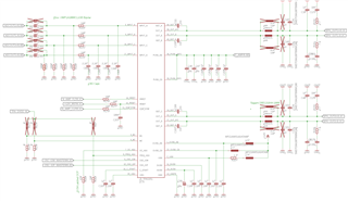
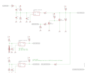
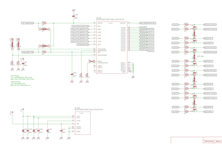
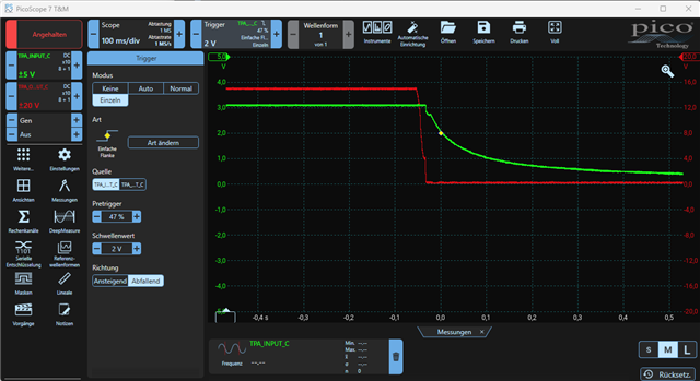
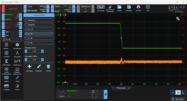
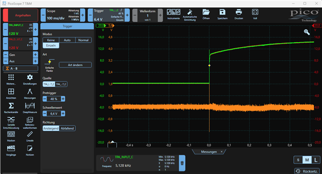
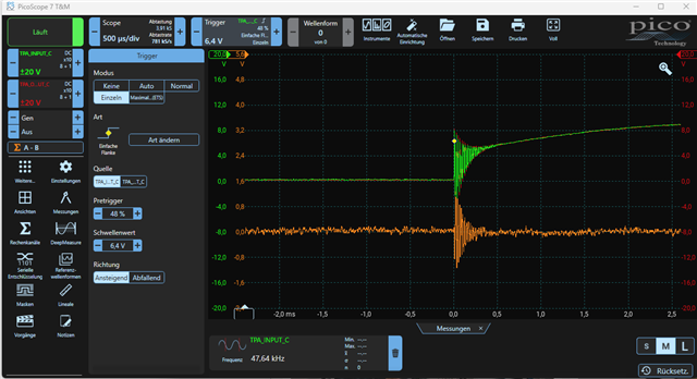
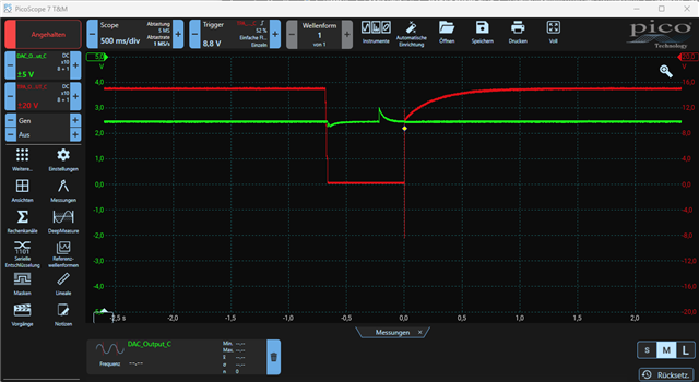
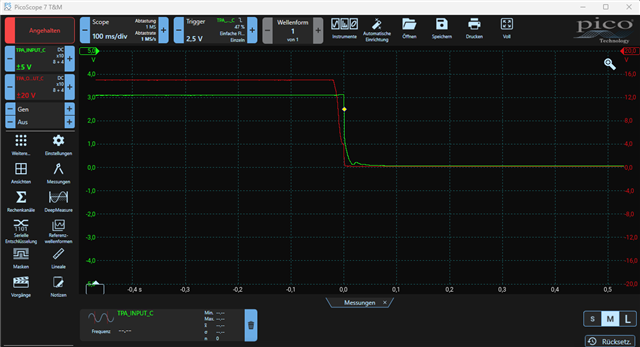
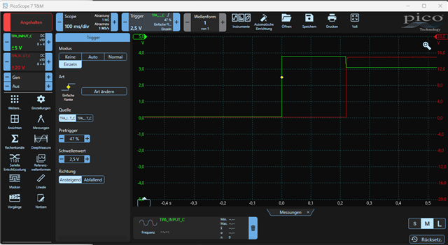
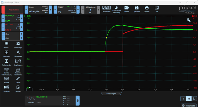
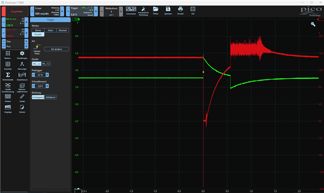
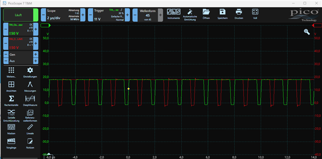
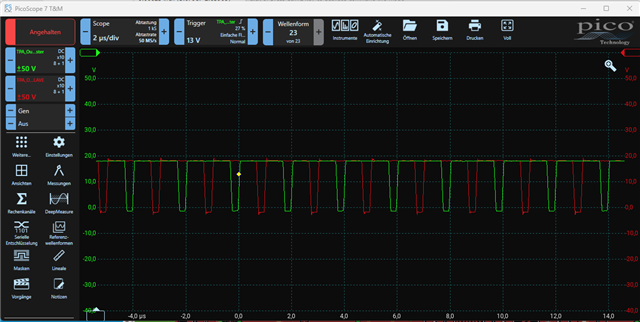
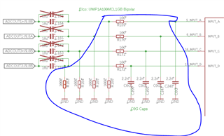
im using two of the TPA3245s hooked up to a PCM1690 DAC, all together controlled via DSP/MCU for a well defined startup/shutdown procedure. The last/first thing in this procedure is to enable the Amplifiers via RESET in order to avoid any noise. Meanwhile during testing, i found actually toggleling the RESET High/Low already triggers a minor, yet audible "plop". Attached are the screenshots of relevant schematics. (take note, the Nets named ADCOUTxxx are actually DACOUTs, dont be confused here)

The Small peaks during RESET on/off seem to cause the small pop noise. Decreasing the C_Start Capacitor down to 33n improved it further, decreasing below 33n did not yield any further improvement. The other way round, the 1u actually did very much worse during turnoff, where for ~100ms white noise occured on the outputs. --> should probably be disregarded due to the very high C_Start Value. [100n is now placed!]

What also was tried:

  • Removing the 2n2 Filter Caps to Ground directly infront of the TPA-Pins --> no Change.
  • Changing the series Resistor between the AC-Coupling Caps and the TPA Pins: (10Ohms .... 470Ohms.) --> no Change.
  • Removing the connection to AC-Cap completely and leaving the analog Pins "open" --> slight improvement, but this is no functional state since nothing is connected
  • Adding additional 100k Pulldown Resistors on the AC-Caps on the DAC-Side --> no Change
  • Turning off the DAC (in RESET) --> no change.

I'd be glad to recieve some help here, since a clear goal is to keep the amp 100% silent during startup/shutdown. As far as i understand from the Datasheet, this should be possible.

Thanks in advance! 

Best regards,

Lukas

  • In addition, here are now a number of measurements which show the input-pins of the TPA, the outputs (each referenced to GND with Load connected), one time with the AC-Coupling Cap connected and one without AC-Coupling Caps connected.

    Orange is the differential signal on the Output Pins of the TPA.

    Seems pretty clear what i do hear at the outputs, both in startup and shutdown. The question would now be how to avoid it :)

  • Another interesting find which might be related here:

    Setting the DAC in RESET via HW Pin results in white noise on the output of the TPA (100% reproducible)

    As shown in the measurement, Green is Voltage on the TPA Input and Red is the Output Signal, measured in reference to GND. The phenomen measured is 1. DAC is turned on and charged the AC-Coupling Cap to 2,5V from its side --> Voltage Overshoot on TPA Pin. This cannot occur in regular use due to the DAC-RESET being coupled to the AMP Reset via SW. Second Jump is when the DAC is going into reset.

    The noise on the red signal afterwards is hearable white noise on the speakers, i cannot trace the rootcause for this at the moment and would be glad for some tips. Together with the pop on/off it might be the same issue.

    Thanks!

  • So, going further down the road, i did find the duty cycles in IDLE both of Master and Slave TPA are not at 50%, but somewhere around 80%, this also could have been seen in the measurements before, since the idle voltage on the load is nearly at full supply. (19V Supply, 16V measured against GND on each positive and negative Terminal.)

    --> All Caps and values around the TPAs have been resoldered, especially for the slave-Amp the voltages VBG, C_Start, AVDD & DVDD have been checked and seem to be OK. (can provide measuremens in case). VBG and C_Start now both are placed with 100nF instead of 1uF as shown in the schematic screenshots

    In a previous Design of mine also using the TPA3245 (which worked flawless regarding Pop/Reset Noise), the static idle duty cycle was found to be 50%. In addition, the previous design has been the basis for the recent one.

    To test the reset-pop "only TPA", the Input terminals of the TPAs have been shorted together (each differential pair), the pop there was also present.

  • Hi Lukas

    thank you very much for you study.

    about the pop noise, how far away from your speaker when you listen the pop?

    the pop is because the voltage difference between outA and outB, usually we want to make sure this difference as small as possible. 

    about your situation, can we take a try below 2 actions to see whether it can be solved.

    1. remove blue area parts, just keep 10uF at the input like our recommended schematic, to see whether it is those parts difference lead to the problem.

    2.change BST cap 33nF to 0.22uF or 0.47uF. 

    it can help increasing charging time at the start up.

    thanks.

    jesse

  • Hello Jesse, i'm setting away ~3m (mid efficiency bookshelf speakers). A 1:1 comparison with the old design was done and the pop in the old design has been a lot less.

    1. I'll try and let you know the outcome. Do you suggest to change the components to the Eval-Design Values, or remove them all together (plus Fitting in a 0Ohm Jumper at the series resistors?)

    2. The Boostrap Node looks nearly flat. I can try and replace the caps, but since this has never been an issue in all of the designs i did with the Akita-Amps, i would love to get a more detailled explanation on this susggestion

    Could you maybe elaborate on what can cause such a shifted idle-dutycycle?

    Thanks,

    best regards,

    Lukas

  • Hey Jesse, Update from my side:

    It seems the 100k Pulldown Resistance (and i double checked the value und solderjoints!) does make the difference here.

    All other values are like in schematic and in place, but removing the 100k Pulldowns R163.... "normalizes" things. Here is Scope recording of one Channel with both 100ks in Place, and one with both 100k removed. Take note, on the one without 100k, the duty cycle is at 50% where it should be in idle, on the other channel, it is off. 

    Is it possible the TPA has some kind of current amplifier or mirror on the Analog Input pins where a static current can distort the PWM Outputs as such? The offset current is as low as 35uA, but seems enough?