This thread has been locked.

If you have a related question, please click the "Ask a related question" button in the top right corner. The newly created question will be automatically linked to this question.

TAS2563: Questions of trade-offs between speaker playback performance and speaker characterization accuracy

Part Number: TAS2563


Hello TI.

I am working with a client's design that uses the TAS2563. The projected volume production is a few thousand units. I started working on the speaker tuning with the TAS2563 DSP. My original plan was to bypass or disable the speaker protection algorithm, and use only the more traditional blocks like EQ and DRC; in that way we could initially ship with the speaker protection disabled, and leave the speaker protection for a future update.

But now I notice that the algorithm is essentially always on, and the methods described in the Tuning Guile SLAA936A do not fully disable or bypass the algorithm (ie. setting the priorities to 1,1,1, or set the Xmax and ThermalLimit to large values). 

As a result, I understand that a successful speaker tuning on the TAS2563 absolutely requires the speaker characterization parameters, either by measuring them with the LB2 EVK or by entering them manually based on the speaker vendor information (<--- please confirm if this is correct).

So, with that in mind, I have a few questions regarding how detailed and how accurate the speaker model needs to be. The questions below are to help us determine which approach we have to take to characterize the speaker enclosure.

  1. I've heard two different approaches for obtaining the final speaker model. The device manufacturer characterized dozens, or even hundreds, of speakers and used the averaged results as the official speaker model. Or, they picked 1-3 golden samples and used the characterization of those for the official speaker model. Do you strongly recommend one approach over the other for the excursion and thermal characterizations? Do you recommend another approach? What criteria do you recommend for selecting the golden samples? Would it be by their Frequency Response and THD, or by their electrical impedance curve?
  2. Is there a significant trade-off between fully characterizing the speaker system with a laser and just entering the single BL factor value from the manufacturer?
  3. In a similar way, I see there is a factory calibration script to get the Re,f0 and Q of the speaker at a known temperature. Does the algorithm rely heavily these values for each individual speaker? Is there a significant trade-off in just entering the same set of values on all devices (ie, re-using the same BIN file on all devices)?

In general, the intention of the questions above is to help determine how much time and effort we should put into the characterization of the speaker. Considering the quickest path: if I use the excursion and thermal characterization from one known-good device (not a golden sample), and re-use the BL, Re, F0, Q for all devices, do we still get some of the benefits of the smart amp (eg, more bass at low playback levels)? Or does this quick approach will eventually force us to turn down the drive level so much that it will negate all of the benefits of the smart amp?  My goal is to hear at least some of the benefits, even if it is just a couple of dB of loudness compared to a regular (non-smart) amp.  

  • Hi Miguel,


    a few comments,

    It is very likely worth your time to get the speaker protection functioning. The audio performance should be noticeably better


    yes, it is not possible to completely bypass the thermal protection. the excursion protection should be able to be bypassed completely. for example if you set the Xmax so high that the device could not reach that excursion at any frequency even when the amplifier is driven rail to rail. however I agree with your assessment, that even when Tmax is 1000C there will be some compression from the thermal controller.


    you are correct, successful speaker protection tuning requires either the speaker should be characterized by the LB2, or the manufacturer can provide these speaker parameters.


    1) It is generally up to the engineer to decide which approach to use to derive the speaker model, because in the end you will need to use a large sample of speakers, say 10-20, to verify that each speaker is being protected(X<Xmax, and Tv<Tmax) with the speaker model and speaker protection tuning. 

    The way that we perform this is to take 20 speakers and characterize them, we take the average of all the speakers parameters, except for the force factor (BL), and the equivalent thermal resistance (Rteq). for BL and Rteq we choose the largest value among the samples. the reason is because a speaker with a high BL will tend to have larger excursion, and a speaker with high Rteq will heat up more for the same input stimulus. this gives us an average model that will be conservative and protect even in the extreme case.

    Once all speakers have been characterized and the average model (with the max BL, Rteq) is found we can move on to verify the protection for each speaker in the sample. for each speaker we will calibrate only the Re. then play music with large bass content to stress the excursion, and music with high average energy, and 3kHz 0dB tones to verify the thermal protection. measure each speaker with a laser to verify the X never exceeds Xmax, and use PPC3 to verify that Tv never exceeds Tmax on any of the speakers. 

    2) If the manufacture provides the BL then It may not be worth spending the money on a laser for this measurement, however the laser is very useful for verifying the speaker protection, and If you plan to do more work with speaker tuning in the future I would urge you to invest in a laser. we use Keyence LK-H050 laser head and LK-HD500 display panel.

    3) the factory line calibration tool (FCT) is doing 2 things, It is calibrating the Re at room temperature on the device, and checking that the Re, F0, Q are within an acceptable range. the user can program an acceptable range, for example +/- 10% and any speakers within that range will pass, their Re will be updated, and the product can be shipped. any that are outside the range will be flagged as "fail" and should be pulled out of production. 

    It is actually very important to calibrate the speaker Re, because the TAS2563 uses the change in speaker resistance to determine the increase in voice coil temperature. where a small difference in resistance represents a large change in temperature. 

    for example the temperature coefficient of copper is ~0.4%/DegreeC. if you use a nominal Re value of 4Ohms, but one speaker has an actual Re of 3.8 Ohms (5% lower than nominal) that 5% can cause the speaker to be overdriven by 12.5C. 5/0.4 = 12.5C,

    If I where to summarize;

    -the ideal case is to do an involved qualification on 20 speaker samples, choose the largest BL, and Rteq, and then rigorously test those parameters on 20 Speakers to verify it is working, and ALWAYS calibrate the Re.  

    However the quick way;

    - characterize 20 speakers, take average value of those 20, leave 10% margin on Xmax, and Tmax, and just calibrate the Re.

    I hope this helps and wasn't too much of a read. 

    Regards,
    Arthur

  • Thanks Arthur. This was very useful information. I am all in for long reads!

    I have to ask a couple of follow up questions, given that the approach I was shooting for does not sound like a great plan after all.

    a) Just to double-check. In any scenario, you are recommending to not skip the Re/F0/Q individual calibration, in order to prevent any given voice coil from overheating, correct?   It sounds like the critical reference parameter used by the amp is Re and the temperature at that time. Sounds like the resulting F0 and Q from the script are meant only for pass/fail criteria at the assembly line, is that right?  

    b) In the case of leaving a 10% margin on Xmax and Tmax, that means setting both values to 10% lower than their know values, right? Does that mean losing around -0.9 dB of the potential max drive on the speaker? If so, that is a good trade-off in our case. But to complete the picture, how many extra dB's do you roughly get with the TAS2563 versus a regular non-smart amp (1.5W rated speaker, 8 ohms)? I want to confirm that even by walking back say 1-1.5 dB, we will still end up with a few extra dB of loudness (and/or bass) compared to a non-smart amp.

    c) When verifying/validating the final speaker model and tuning on the samples, is it possible to read the value of Tv from the TAS2563 in the DUT (by i2c, an internal script or some other connection)? Or will I have to use the LB2 externally wired to the speaker in the device? I assume that calibrating for Re would already be saved onto the device itself (after running the factory calibration script), or entered manually in the PPC3 GUI, right? Any additional methods for entering Re during the validation tests? For example, saving or pushing a new BIN file into the device's memory?

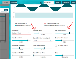
    d) Regarding setting Xmax to a high value. I have done some preliminary tuning of the device using the TAS2563 eval kit, but when I set the Xmax to say, 10 mm, the amplifier seems to want to amplify the signal almost constantly. I interpreted this as the amplifier "thinking" that it still had plenty of room to drive the speaker. With a fake large Xmax value, what is the voltage limit that it will amplify to? Will it amplify it to the max voltage level set by the "Amplifier Level" register setting?  Or, will it ignore the "Amplifier Level" and go all the way to the maximum voltage amplitude that 'fits' inside the VBST rails? (see screenshot below) I have to do more tuning and testing, so it would be very helpful to know what is the correct behavior I should see from setting Xmax to an artificially high value during the tests.

    Thanks again for your detailed response. It is very helpful to decide our next steps.

  • Hi Miguel,

    a) yes your understanding is correct

    b) your math seems about correct, one thing to note is that speaker temperature has a linear relationship with power, and speaker excursion has a linear relationship with voltage. So the number may be different if you calculate using voltage ratio for Xmax derating, and power ratio for Tmax derating. 

    One large benefit of the smart amp protection is that you are able to boost the frequencies below the speakers F0 more aggressively without much concern of damaging the speaker due to the excursion protection. the Loudness increase from the thermal protection is dependent on the tuning that you have already done. Maybe you have tuned it in such a way that the speaker is already being driven very hard, but hasnt been tested long enough to be damaged? If that is the case the benefit may not be obvious. With that said in the early days of TAS2563 we have done demos on commercially available products and where able to beat the current performance by ~6dB in the base, and ~3dB in the mids and highs  

    c)the Tv can be recorded using the verification window in PPC3 even without the LB2 connected. yes after running the factory calibration script the Re will be saved into the device. either use the FCT tool or enter it manually to PPC3.

    d) the maximum output is limited by both the Max boost and the amplifier level, obviously the amplifier output cannot exceed the boost voltage. The amplifier level describes the maximum full scale output voltage. i.e. 12dBV means 12dB larger than 1Vrms . 12dBV = 4Vrms ~= 5.64Vpeak. this means when no attenuation from Excursion or thermal protection is applied the output should be 5.64Vpeak at all frequencies (11.28Vp-p)

    Regards,

    Arthur

  • This is all very helpful. I think these might be my final question for this topic. They are regarding Item D.

    The document SLAA857 (speaker protection algorithm) says that the protection algorithm attenuates the input signal when the calculated excursion exceeds Xmax, otherwise it leaves it unchanged.  So, the excursion protection only limits the signal and does not boost, right? Does the temperature protection acts as a signal limiter too, or does it attempt to amplify the input signal at any point? If the excursion and thermal protection algorithms are "subractive" only, it will give me much more confidence to be able to predict or control the maximum voltage that the speaker ever sees.

    And in that note, it's good to know that the "Amplifier Level" value is basically the DAC gain of the amp. So, no matter what happens upstream (EQ, DRC, X protection, T protection, etc), the output voltage cannot exceed the level set by "Amplifier Level", correct?  If I need to modify the "Amplifier Level" at some point in the development, do I need to re-run the characterization of the speakers with the new "Amplifier Level" setting, or does the algorithm adjusts itself to the new level?

    Thank you

    Miguel

  • Hi Miguel,

    The speaker protection is only subtractive.(the gain from them is either 0dB or a negative value). this just means you can be aggressive with your tuning and it will act as a hard limit. 

    Yes, the output will never exceed the Amplifier level. If you do change the Amplifier level there is no need to perform the speaker characterization again. the Amplifier level register is used by the algorithm to correlate a digital dB value into a meaningful voltage.

    you should understand that the speaker model we use (Thiele Small/ Lumped physical/ Thermal models) are industry standard, and are completely agnostic of what amplifier is used.  

    Regards,
    Arthur