This thread has been locked.

If you have a related question, please click the "Ask a related question" button in the top right corner. The newly created question will be automatically linked to this question.

PCM1808: strange noise on audio recording

Part Number: PCM1808


Hello,

I'm developing a circuit based on PCM1808. It is basically a PCB with an analog MIC, a preamplifier and the PCM1808 to encode analog signal to digital I2S interface.

I started recording a 880 Hz sine audio source, but the PCM1808 has a strange behaviour. I measured all the supply voltages and they are stable, without significant noise. I put a probe on ADC IN signal and this is what I see:

But when I record it the signal is very noisy and I think that something is wrong.

This is the audio signal recorded from I2S interface:

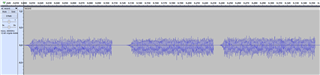
Zooming out the signal, I can't figure out why the signal seems to be "pulsed" as you can see in this image:

I also attach the two audio files I recorded. one is "record.wav": it is a 880 Hz sine recording. the second attachment is "silence.wav", recorded in a silent room.

Could you help me please?

  • In order to help identify the problem, can you provide some more details on your project?

    -What device is the I2S interface connected to?

    -Is the PCM1808 in master or slave mode?

    If the PCM1808 is in slave mode: are your audio clocks (SCKI, BCK, LRCK) synchronous to each other and with correct timing and frequency relationship?  The exact operating frequency is not as critical as the ratio between them.  For example, LRCK of 48kHz, BCK 3.072MHz, SCKI 12.288MHz.  In this case, BCK is exactly 64x, and SCKI exactly 256x the LRCK frequency.  Ideally BCK and LRCK would be divided from SCKI.

  • Dear Jeff,

    The I2S will be connected to a DSP, but at the moment we are testing the audio codec part, so it is connected to the I2S interface of a raspberrypy.
    Just to be more precise, I'm also testing a mems I2S mic on the same rasperry interface, to compare with PCM1808, so I am sure that the digital interface is good.

    The PCM1808 is in slave mode (MD0, MD1, FMT connected to GND). The SCKI PIN is driven by a  SN74LVC1GX04DCK with a 24,576 MHz crystal.

    I can share with you the schematic circuit, but I need to keep it confidential, How can I proceed?

  • This will work, but only if the Raspberry Pi (or DSP, in your final design) is able to generate its I2S clocks from the same 24.576MHz reference connected to the SCKI pin on the PCM1808.  If LRCK and BCK are not synchronous to SCKI then the drift between the two oscillators will periodically force the PCM1808 to mute as it tries to re-synchronize.

    Does your MEMS microphone output a PDM bitstream or PCM samples?

    I think there is a way to send private messages on this forum, but I'm not sure.

  • Ok, maybe there is something I cant understand. we need to replace an INMP441 with a more accurate MIC (with higher AOP up to 130 dB) so we decided to develop a cusom PCM1808 PCBA.

    The INMP441 does not require any SCKI clock, that's why we are using the XTAL (like the EVM do).

    Is it wrong?

  • The XTAL on the PCM1808EM is usable when the device is in master mode.  It then generates BCK and LRCK by dividing the frequency of SCKI, and provides them as outputs on the corresponding pins.  This would require the Raspberry Pi or DSP to accept BCK and LRCK as input signals in addition to the audio data provided on DOUT.

    When in slave mode, the PCM1808 uses SCKI to run the internal oversampling Delta-Sigma modulator and digital filters, and BCK/LRCK are used to control the I2S interface and digital filters.  For proper operation these signals must be synchronized, otherwise dropouts and noise will occur as the two clock domains drift and the PCM1808 mutes and tries to re-synchronize internal operations.

    The MEMS microphone would have to derive its system clock from the 64x BCK input.  The PCM1808 requires a separate 256x, 384x, or 512x system clock. (This is typical of most oversampling ADCs, not just the PCM1808.)

    I did some quick looking, and I don't think the Raspberry Pi will generate an appropriate system clock, but many DSP and MCU devices do.  If the device in your final design can generate a suitable system clock, --or-- can accept SCK and LRCK as input signals, then it will work correctly.

    I hope this is helpful!

  • Hi ingDIY,

    Jeff's advise so far is sound. Do you you want a TI engineer to review the schematic? We can do that internally and away from the public forum.

    Best regards,
    Jeff McPherson

  • Thanks Jeff.
    So if the PCM1808 is in slave mode there is no way to avoid that the SCKI signal is provided by the master?

    I suppose that you are talking about datasheet section 7.3.3:

    7.3.3 Synchronization With Digital Audio System
    In slave mode, the PCM1808 device operates under LRCK (pin 7), synchronized with system clock SCKI (pin 6).
    The PCM1808 device does not require a specific phase relationship between LRCK and SCKI, but does require
    the synchronization of LRCK and SCKI.
    If the relationship between LRCK and SCKI changes more than ±6 BCKs for 64 BCK/frame (±5 BCKs for 48
    BCK/frame) during one sample period due to LRCK or SCKI jitter, internal operation of the ADC halts within 1 / fS
    and digital output goes to zero data (BPZ code) until resynchronization between LRCK and SCKI occurs.

    Yes, I think that the RPi is not able to provide the right SCKI signal. I'm wondering if is possible to use the PCM1808 in master mode with RPi.

    Thanks!

  • Yes please, advises are good, but just to double-check I would like to send you the schematic.
    How can I proceed?
    Thanks!

  • Please send me your schematic on sanjay.dixit@ti.com.

    In addition can you please send me details about the incoming timings to the device?

  • Thanks! I answered by mail.

  • As we shall now coninue our debug by e mail ,i am closing this thread.