This thread has been locked.

If you have a related question, please click the "Ask a related question" button in the top right corner. The newly created question will be automatically linked to this question.

TLV320AIC3109-Q1: Single Channel Usage

Part Number: TLV320AIC3109-Q1
Other Parts Discussed in Thread: TAS2505-Q1

Hello team,

We are planning to use TLV320AIC3109-Q1 and TAS2505-Q1 in our design and we only have a single mic and single speaker application.

We have few questions:

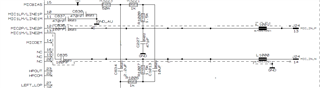
1. Can we use only MIC2P and MIC2M for our usage and terminate MIC1 channel?

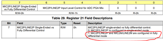
2. Are there any technical differences between MIC1 and MIC2?

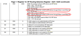
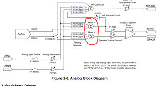
3. W.r.t output, we are planning to use RIGHT_LOP and RIGHT_LOM and this will be connected to AINR and AINL of TAS2505-Q1. Is this okay?

4. Are there any technical differences between RIGHT and LEFT channels?

5. If there are differences between MIC1 and MIC2, and RIGHT and LEFT channels, which one do you prefer to use for our application?

Thank you in advance.

  • Hello Mayur,

    Thank you for reaching out. 

    1. No, you can ground single ended inputs to AVSS. For unused inputs, connect a 0.47-µF capacitor to AVSS.
    2. There are no differences between MIC1 and MIC2
    3. RIGHT_LOP and RIGHT_LOM are fully differential, while AINR and AINL of TAS2505-Q1 are single end inputs by default. Please see the TAS2505 Application Reference Guide on configuring these as a differential input, if desired.
    4. Right and Left Channels are the same.
    5. There are no differences, however, the TLV320AIC3109-Q1 does allow them to be routed/configured separately if desired. Please make sure unused analog inputs are AC coupled and grounded and unused outputs are left open, as recommended in the datasheet. 

    I hope this helps.

    Best,
    Andrew

  • Hello Andrew,

    Thanks for the feedback. 2,4,5 points are clear.

    1. I've attached a snippet from schematic.


    W.r.t datasheet, I think the MIC2 channels can be connected to Differential Mic input and can be configured in SW. While MIC1 is coupled with caps.

    Please let me know if the understanding is correct and the connection is ok or not.

    3. Is the highlighted setting to be followed?

    • If yes, what is the difference between 0110 and 1001?
    • Does Mixer A and Mixer B refer to Mixer P and Mixer M?

    I kindly request you to provide your feedback.

  • Mayur,

    1. The configuration in the schematic and circled register setting is correct.
    2. (#3) I can confirm that Mixer A and Mixer B refer to Mixer P and Mixer M
      1. With regards to Page 1 / Register 12 settings:

    Bits D7-4 are used to control the routing from AINL/R to SPKP/M. The routing is controlled by the bits D7-4 in  Page 1 / Register 12 (blue box below) and each bit can be visualized as a switch. 

    The two circled portions of the register settings (your screen capture above) are functionally the same and both route AINL/R differentially when setting D7-4 as 0110 or 1001. This is more easily demonstrated in the GUI (screen captures below). 

    D7-4 set to 0b0110:

    D7-4 set to 0b1001:

    As you can see both settings drive the speaker outputs differently but are inverse of each other. 

    I hope this helps.

    Best,
    Andrew

  • Hello Andrew,

    Thank you very much for the detailed feedback.

    1. RIGHT_LOP connected to AINR and RIGHT_LOM connected to AINL. Is this the correct configuration or it needs to be swapped?

    2. Is there any recommended impedance for all the differential signals (Mic input to Codec, Codec to Amp, Amp to Speaker)?

  • Hi Mayur,

    Andrew is out of office today and will answer your questions on Monday.

    Thanks for your patience,
    Jeff McPherson

  • Hello Mayur,

    Thank you for your patience. 

    1. RIGHT_LOP connected to AINR and RIGHT_LOM connected to AINL. Is this the correct configuration or it needs to be swapped?
      1. Yes, this is a correct configuration. 
    2. Is there any recommended impedance for all the differential signals (Mic input to Codec, Codec to Amp, Amp to Speaker)?
      1. For best results match trace length for all differential traces on the PCB
      2. Mic input to Codec - select the feed-forward resistance value that is closest to the microphone impedance.
      3. Codec to Amp - no specific impedance recommendation, however, please use a series capacitor to AC couple the CODEC outputs from LINE inputs.
      4. Amp to Speaker - no specific impedance recommendation, please use the datasheet guidelines. 

    I hope this helps.

    Best,
    Andrew

  • Hello Andrew,

    Thanks for the information.