Dear TI tech support,
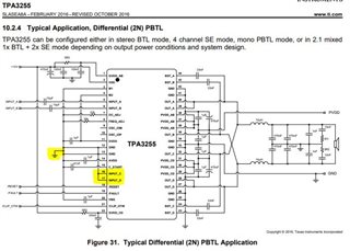
Using TI EVM as a reference, I have design my own PBTL amplifier (file attached).
Unfortunately, when powering the device (using 24Vdc) the amplifier stays in FAULT low and I can't make the device work properly.
Toggling /RESET doesn't clear the /FAULT status.
Here is the config at the moment:
Freq Adj : 10K ohm
OSC IOM & OSC OIP left open
Cstart : 47nF
Inputs signals:
PVDD = 23.1V
GVDD_AB = GVDD_CD = VDD= 12V
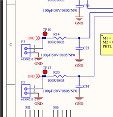
INC = IND = GND
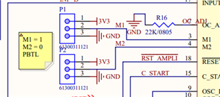
M1 : GND
M2 : 3V3
/OTW = 3V3
/FAULT = 0V
So looking at the possibilities why the device stays in FAULT=0V, I found in the datasheet:
Option 1: Pin-to-Pin Short Circuit Protection (PPSC).
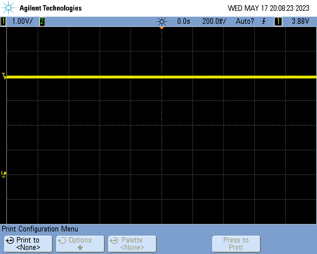
Amplifier output are not shorten to GND or PVDD since PWM_A = PWM_B = OUT_A = OUT_B = 7,9V and there is no resistive load to PVDD.
Still it seems that the device is blocked in PPSC detection.
Option 2: Undervoltage Protection (UVP) and Power-on Reset (POR)
Not possible since all the supply voltage are in the range of stated values reported in the Electrical Characteristics table (see above).
Option 3: Stuck at Fault due to OSC_IO input signal frequency drops below minimum frequency.
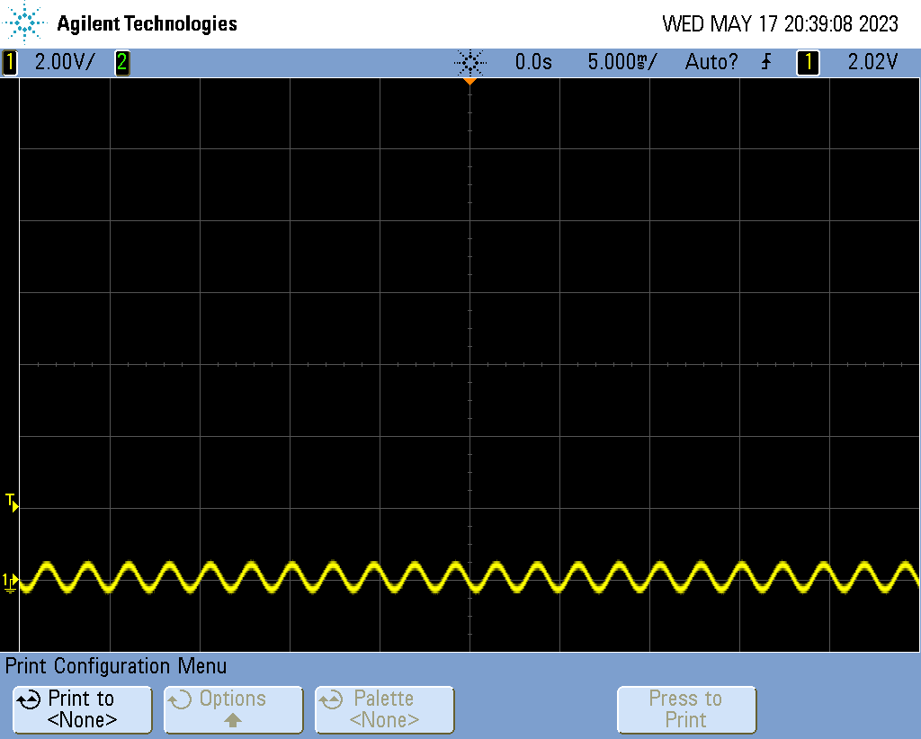
OSC_IO is left open and its voltage is 1.6V.
Well that's it! If you have any suggestion why the device reacts like this, i would love to know about it.
Thank you for your time,
Best regards,