Other Parts Discussed in Thread: TPA3255, TAS5634
Hi,
I am using the tpa3255-Q1 to amplify a 40 kHz signal in BTL mode. I wanted to connect a transducer array to the amplifier and the expected resistance of the array was calculated to be around 24 ohms. I designed my LC filter accordingly, and got an inductance of 42 uH and a capacitance of 47 nF.
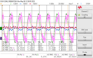
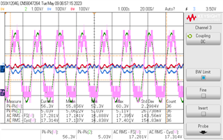
Initially, I tested the amplifier with a 24 Ohm power resistor, later with a 30 Ohm as well because the array got smaller. Here are the outputs for the pure 40 kHz sine input:
24 Ohm
30 Ohm

The output is the pink signal and the input behind is the green one.
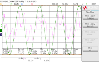
Since this looked good, I connected my transducer array, however the output was distorted. I realized it is probably because of the capacitance of the transducers (I used piezoelectric transducers with an overall capacitance of 42 nF). Therefore, I took off the output capacitors from the amplifier board but still got a distorted result:
I am unsure of why this happens. Any advice to improve?
Best regards,
Zora


