This thread has been locked.

If you have a related question, please click the "Ask a related question" button in the top right corner. The newly created question will be automatically linked to this question.

TAS2770YFFEVM: TAS2770YFFR

Part Number: TAS2770YFFEVM
Other Parts Discussed in Thread: TAS2770,

Hello Customer Support Team,

We are currently performing PoC on TI TAS2770 audio amplifier and need your assistance for following.

The details of the device are as follows:

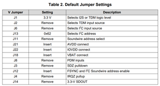
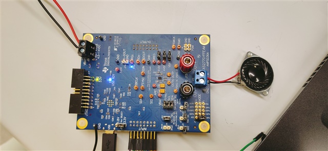
Device Name: TAS2770YFF Evaluation Module

Model Number: TAS2770YFFR

Host machine: Windows 10 OS

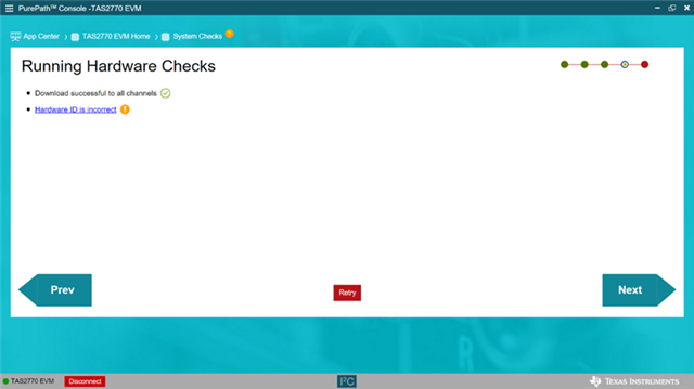
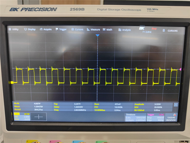
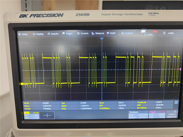
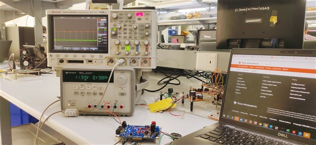
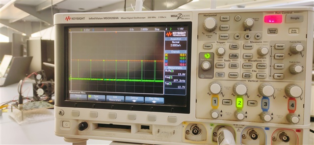
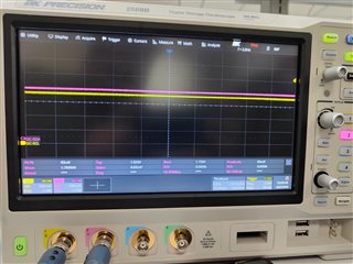
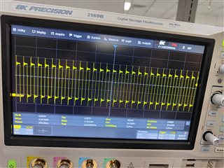
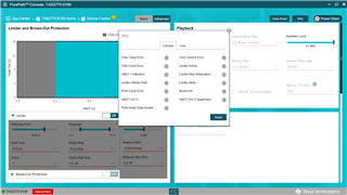
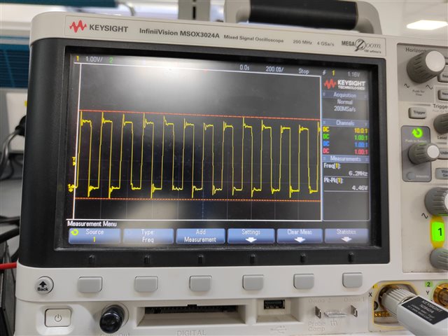
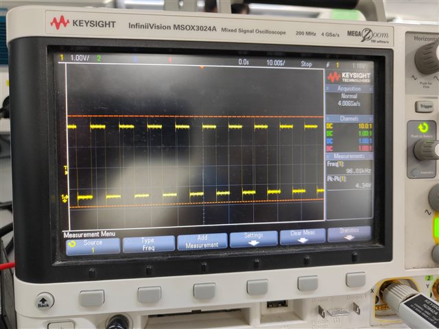
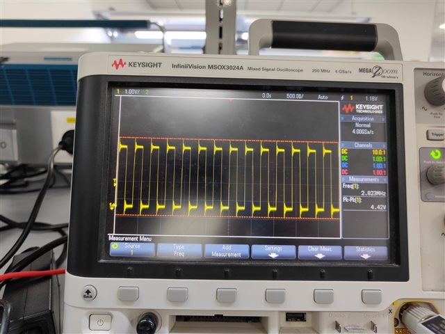
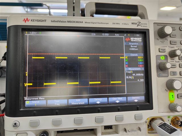
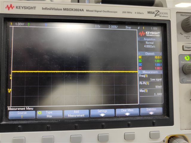
Currently, we are just trying to play from windows as Host machine and using Pure Path Console 3 application. When we play something on Windows machine, we can see SDIN data signal is active and there is some data passing through but still we cannot hear anything on speaker.

If you require any additional information, please do let me know.

I look forward for your prompt response and resolution of my request.

Thanks & Regards

  • Hi, 

    to play through the EVM you will need to connect via USB and power the EVM. make sure it is selected as the audio device and is not muted. 

    make sure the jumpers are configured per the EVM users guide

    open PPC3, select the TAS2770 EVM application, and press "connect" in the lower left corner of the GUI

    then navigate to the Device control panel, and press " Power Up" in the upper right corner of the GUI.

    If you are using an I2C address other than 0x82 or 0x84 then you will need to change the I2S slot configuration to mono left/right channel

    Regards,
    Arthur

  • Hello,

    I have done this already and it didn't help me out to get the audio from the speaker. 

    Currently we are using an I2C address 0x82.

    I am using slou408 [PPC3 User Manual].pdf as a reference as provided by the TI. 

    I have followed all the procedures as given in this manual, but it didn't help me out.

    And also, when we run the system check through PPC3 we are getting the incorrect Hardware ID. Will this Can be some issue for us?

    We are getting perfect sbclk , fsync and SDIN but at the j10 we are just getting switching frequency of TAS2770 i.e. around  347 KHz & that to at very low voltage level although we are providing 12V at VBAT .

    We got the following waveforms at

    *SBCLK


    *FSYNC


    *SDIN


    Regards,

    Shubham        

  • Hi Shubham, 

    this EVM has MUXs to switch from internal I2S(USB) or external I2S(J7). Are you probing these I2S signals at the test points continuous with the device pins? TP1,3,4?

    you say that the Class-D output is switching to a voltage lower than VBAT. Is the VBAT jumper J18 installed?

    Can you share a image of your EVM so I may see the Jumper settings?. Since the output is switching It means the device has been programmed and is in active mode, 

    Regards,
    Arthur

  • Hello Arthur,

    Thanks for the response. We are probing the signals at output connector J5. J18 is installed. I am sharing the images of my evm and output waveform measured at j10. we are still not able to hear any voice from speaker.

    set up image:

    output waveform at j10 out + 

    Regards,

    Shubham

  • Hi Shubham,

    Today is a TI US holiday. Arthur will get back to you on Tuesday.

    Thank you for your patience,
    Jeff McPherson

  • Hello Jeff 

    Goodmorning

    Due to the issue above mentioned , we have purchased another board ( TAS2770YFFEVM AMPS036C  )and its working standalone . But we are not able to find any schematic of the same . 

    We are only able to find data regarding to "A"  Version i.e. TAS2770YFFEVM AMPS036A on TI website.

    Can you provide us the datasheet of the "C" version board of the TAS2770YFFEVM  i.e. TAS2770YFFEVM AMPS036C.

    Thanks in advance

    Shubham 

  • Hi Shubham, 

    the revision C EVM is working as expected?

    Please find the attached schematic for the Rev.C EVM

    AMPS036C(001)_Sch.PDF

    Regards,
    Arthur

  • Hello Arthur,

    Revision C evm is working as expected. Thanks for the schematic . 

    I had gone through the  REV. C. datasheet and i observed you have ADDED 1.8V BYPASS CIRCUITS FOR I2C in REV. B. . Can you explain the reason of this circuitry addition. 

    And We are still not able to listen music from REV A board even though we have kept the same configuration settings as we have kept in REV C. Board. So can  you help me regarding that and have you observed similar issues in other cases also. 

    Is this alteration in REV C. is the solution of our issue ?

    Regards,

    Shubham

  • Hi Shubham,

    I'll Arthur is out of office for some days, I'll follow up with you on this thread.
    I'm going through the history above, and will compare the design from revA vs revC. I'll get back to you by the end of the day tomorrow.

    Best regards,
    -Ivan Salazar
    Applications Engineer

  • Hello Ivan,

    Is there any update on the above query ?

    Regards,

    Shubham

  • Hi Shubham,

    The I2C bypass circuitry introduced in revB should only affect the operation of the EVM when using external I2C signals and VCC select as 1.8V.
    In addition to that, it seems your revA board is able to initialize the device (you can see Class-D switching) but audio is not working, which would tell it is more related to I2S/TDM than I2C.

    A few follow up debug tests:

    • Can you check I2S and I2C signals on both of your boards to compare if the levels are the same?
    • From your board picture, IRQ LED is enabled. Can you use PPC3 -> Device Control panel, power up the device as you normally do and then click on IRQ button on top-right. Read the latched flags and please share which ones you see enabled.
    • Also from the picture you shared, I can see some cables connected on the Input header connector, I don't these are being used at all since you're using USB mode, correct? Do you see any difference if disconnecting these cables?

    Best regards,
    -Ivan Salazar
    Applications Engineer

  • Hello Ivan

    Thanks for the support. After doing the debug tests as suggested by you we observed .

    1. RevA board doesnot connect to PPC3 configuration directly we need to connect it . On contrary REV C board gets connect by itself.

    2. In both boards when we select 3.3V configuration of VCC we get voltage levels of 1.8V at I2C SCL & SDA . 

    3. As mentioned in your 2 point we connected the REV A Board with PPC3 and we didn't get any latched flags over their on clicking the IRQ Button.

    4. We tested the board standalone and removed all the cables from input header but the response was same . so we were not able to find the issue .


    Can you tell us What can be the expected issues in this board. As we need to validate the schematic of Tas2770 REV A board that we are going to use in our design.

    Thanks & Regards,

    Shubham

  • Hi Shubham,

    Can you comment on why would you use revA schematic instead of revC which actually works OK?

    Can you also check I2S signals on both boards? As mentioned, it seems I2C works OK on both boards because you can see the Class-D switching at least, but we're more interested in looking at the audio data, you may use the orange test points to check SBCLK, FSYNC and SDIN signals. Does SDIN change significantly when you try to play audio through USB?

    Regarding the IRQ flags, I assume you clicked on "read" button as well, correct?

    Best regards,
    -Ivan Salazar
    Applications Engineer

  • hi Ivan ,

    We have observed that in standalone condition In rev c Board which is working the FSYNC , SBCLK , SDIN remains at 1.8v before playing music but in REV A board which is not working in that SDIN remains at 0 V .

    Before playing music in REV A board

    SBCLK: 

    FSYNC:

    SDIN:

    OV

    After connecting with PPC3 and playing music:

    SBCLK:

    FSYNC:

    SDIN:

    REVC board before connecting with PPC3 we are getting 1.8v at SBCLK,FSYNC & SDIN

    Is there any issue in XMOS? This issue is taking so long so Is there any provision to replace the A board ?

    Thanks & Regards,

    Shubham

  • Hi Shubham,

    Sorry for the confusion, I though you already had 1 revA board and 1 revC board. Is that not correct?
    We can ship a new EVM if required, it should be the latest version.

    If xMOS programming is the issue, we can re-program within TI but unfortunately not on customer side.

    Best regards,
    -Ivan Salazar
    Applications Engineer

  • Hello Ivan 

    Actually we had ordered two boards separately. First Time it came of rev A which is not working till date. Then we ordered 2nd time same EVM , We Received REV C board . After receiving the other board we came to know that there are 3 different revision boards of same EVM. So if the REV A  Board is replaceable then what is the procedure as reprogramming the Xmos option would not be possible as per your last conversation.

    Regards & Thanks

    Shubham

  • Hi Shubham,

    We can provide a second EVM to replace the revA you got in the first place.
    I'll send an invite so we can share the shipping address and other details over private message.

    Best regards,
    -Ivan Salazar
    Applications Engineer