This thread has been locked.

If you have a related question, please click the "Ask a related question" button in the top right corner. The newly created question will be automatically linked to this question.

DIX4192: Problems sending and receiving user data through SPDIF

Part Number: DIX4192


Hi team,

One of our customer's issues, could you please provide some troubleshooting suggestions?

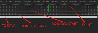
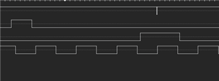
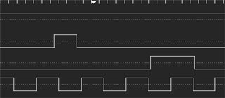
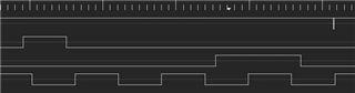
DIX4192 uses SPDIF's STATE bit to send and receive user data. Currently, data can be transmitted through SPDIF, but data cannot be received. Use oscilloscope capture can see the user data in STATE bit.

Configure GPO3 as RX BLOCK START,GPO2 as RX INT, and GPO1 as TX INT. Configure the corresponding register.

Open the interrupt of RBTI, receive the block start signal, set RXBTD to 1 after 2ms delay, wait for the interrupt of RBTI, read the user data and status register after entering. 

The current issue is that the data sent by the main control board can be received, while the data sent by DIX4192 can occasionally be received by the main control board. What is the reason for this?

Is it possible that there is an issue with the block start timing? Start sending blocks according to this setting:

Best Regards,

Amy Luo

  • Hi Amy, from the description it seems there is an issue with the block starting timing in their system as many of the issues in these ICs are timing related.

    They can send me the clocking and DIT block start timing , and will take a look at it.

    Regards,

    Arash

  • Hi Arash,

    The following is customer feedback:

    I'm so sorry not reply you until now, but I found that there is a problem with the board. I have re-layout it and found that the problem still exists.

    I set two boards, one as the master and the other as the slave. An LED light was connected to the LOCK pin to indicate the Lock status. I found that the LED display of the master was unstable, while the LED of the slave was constantly on.

    Turn on the MBTI interrupt, set GPIO1 to TX INT, and the following is the timing chart for grabbing.

    Below is the timing for the first green box to zoom in, with a TX INT trigger missing in the middle

    The timing of the second green box to zoom in, with two TX INT triggers missing in the middle

    My TX BLOCK START is placed in the RX START BLOCK interrupt, and the following is the TX BLOCK START processing

    while(1)
    {
    switch(state)
    {
    case 0:
    if(TX_SYNC_Get()==1)
    {
    state=1;
    count=0;
    }
    else
    {
    count++;
    if(count>100000)
    {
    TX_BLS_Clear();
    state=0;
    count=0;
    return;
    }
    }
    break;
    case 1:
    if(TX_SYNC_Get()==0)
    {
    state=2;
    TX_BLS_Set();
    //TX_BLS_Clear();
    count=0;
    }
    else
    {
    count++;
    if(count>100000)
    {
    TX_BLS_Clear();
    state=0;
    count=0;
    return;
    }
    }
    break;
    case 2:
    if(TX_SYNC_Get()==1)
    {
    state=3;
    count=0;
    }
    else
    {
    count++;
    if(count>100000)
    {
    TX_BLS_Clear();
    state=0;
    count=0;
    return;
    }
    }
    break;
    case 3:
    if(TX_SYNC_Get()==0)
    {
    TX_BLS_Clear();
    state=0;
    count=0;
    return;
    }
    else
    {
    count++;
    if(count>100000)
    {
    TX_BLS_Clear();
    state=0;
    count=0;
    return;
    }
    }
    break;
    default:
    break;
    }
    }
    }

    Could you please help me check where the problem is and how to handle it? Thank you

    By the way, if TX BLOCK START is masked during the RX BLOCK START interrupt, the LOCK indicator LED on the master end can be stable.

    Best Regards,

    Amy Luo

  • Hello Amy,

    The  fact that if  TX BLOCK START is masked during the RX BLOCK START interrupt, the LOCK indicator LED on the master device is stable sounds like the device is okay. Also looking at the plots you sent, something in the instruction sent to device might be causing it. 

    Since I am not sure what all these states and cases are meant, to debug I would repeat the condition of one  case for all other cases  to see if problem is related to instruction of a specific case . This needs to replace the cases few times to see whether a specific  instruction in one of the cases causing the temporary halt.

    The lock output is active only when both the AES3 decoder and PLL2 indicate a lock condition. If there is no instruction to  interrupt from above, check to see why AES3 decoder and PLL2 might not be in lock condition.

    Few registers that he can check :Register 02: Global Interrupt Status (Read-Only) Field Descriptions

    Register 11: Receiver PLL1 Configuration Register 3 Field Descriptions

    Also see Figure 17. DIR Channel Status and User Data Serial Output Format Through the GPO Pin.

    Regards,

    Arash

  • Since i will be out of office for 10 days, I close this thread for now  and you can open it if you need more help or have any question . 

    Regards,

    Arash