This thread has been locked.

If you have a related question, please click the "Ask a related question" button in the top right corner. The newly created question will be automatically linked to this question.

TAS5825P: Boost Converter selection for Hybrid-Pro

Part Number: TAS5825P
Other Parts Discussed in Thread: TAS5825M,

Hi:)

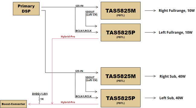
I am currently working on a design that uses 2x TAS5825P + 2x TAS5825M and have now come to the point where selection of a suitable Boost-Converter is required.

However I did not find any documentation on how to choose a proper Boost-Converter for use with the Hybrid-Pro feature of the TAS5825P and would like to get some help and/or recommendations if possible.

----------------------

Q1: What minimum Switching frequency is recommended? (TAS: 384KHz)

Q2: Are there any Loop-Gain requirements?

Q3: Since I will be using 2 Fullrange drivers and 2 Subwoofers with different output requirements, would it be beneficial if I choose 2 separate Boost-Converters instead?

Q4: Are there any 2-Phase Boost-Converters available for this application?

----------------------

My design:

Input: 6.40V to 8.20V (2S Li-Ion)

Booster output: 9.80V to 20V 6.5A Peak

-

1-TAS5825M, Driving 4Ohm at 10W RMS

2-TAS5825P, Driving 4Ohm at 10W RMS (Hybrid Pro)

3-TAS5825M, Driving 2.6Ohm at 40W RMS

4-TAS5825P, Driving 2.6Ohm at 40W RMS (Hybrid Pro)

All in Mono-Mode, 500Hz Crossover.


Thanks!

  • hi,

    thank you for your question.

    Q1: in our devices, 384k is the minimum switching frequency.

    Q2: no requirement for loop gain.

    Q3: for your power is not that high, you can config 2 devices GPIO to open drain and connect them together.

    Q4: for the power is not that high, no need using 2-Phase boost.

    tks

    jess

  • Hi Jesse:)

    Thanks for your reply!

    As for Q1; the amplifier frequency is set to 384KHz, based on this what should be the minimum switching frequency for the booster?

    --

    As for Q2; Okay thanks:)

    --

    As for Q3; I am aware of the possibility for connecting 2+ TAS5825P together for Hybrid-Pro, however since the output of the booster will fluctuate even though not all amplifiers need it, won't it introduce noise and less efficiency?

    --

    As for Q4; the output power might not be very high, but a 2-phase booster will provide less ripple and more stable output, especially when input voltages are low like mine. Are there any 2-phase boosters that are compatible for this application?

    --

    Added question Q5; are there any specific considerations when selecting a boost converter for this application, or are pretty much all Boost-Converters suitable?

    Thanks!

  • Hello Diederik,


    1. The switching frequency of the boost not related to the amp, usually above 100kHz frequency is used for a smaller inductor but this isn't a specific requirement
    2. resolved
    3. Can you clarify why you are using a mixture of TAS5825M and TAS5825P, i wouldn't connect the boost controlled by Class-H to non Hybrid-Pro supported devices, due to these variations in the booster due to the control.
    4. We don't have specific recommendations but you can reach out to the power management forums and outline your output power requirements, output/input voltages, current requirement, and a need for a sync pin for the class-h control. Using a 2-phase boost depends on the output power needs.
    5. Make sure the clamp time of the boost to the necessary voltage is smaller than the class-h delay.

    best regards,


    Luis

  • Hi Luis:)

    Thanks for your reply!

    -

    For Q1; Shouldn't the switching frequency be a certain amount off the amplifier switching frequency?

    For example, if the amplifier operates at 384KHz, and the booster operates at 385KHz, wouldn't that create unwanted noise since its only 1KHz apart?

    Also, if the booster operates at lets say 100KHz and the amplifiers at 384KHz, wouldn't that mean the booster will not be able to respond as quickly as the amplifiers?

    I also noticed that in the TAS5825PEVM the booster operates at 440KHz, what is the reason for this?

    -

    For Q3; I'm using the TAS5825M for excursion limiting and dynamic EQ's, this processed signal will than be send out using the SDOUT to the TAS5825P for the Hybrid-Pro feature. The TAS5825M will not be used for the Hybrid-Pro feature, only the TAS5825P. I included a simple block-diagram to show this.

    Note: The delay of the TAS5825P for the hybrid-Pro will be compensated for using a different DSP ('PrimaryDSP' in diagram).

    -

    For Q4; Alright, I'm currently planning on using a LTC3784 Booster IC, I assume this IC would be fine than?

    -

    For Q5; So in my case, the booster must be able to swing from 9.80V to 20.20V in under 4ms (max Class-H delay) and be steady, correct?

    -

    Thanks!

  • Hello Diederik,

    1. The TAS5825 has a high PSRR so this shouldn't be a concern. The lookahead delay also gives the boost controller time to respond

    3. The TAS5825P has the lookahead delay in the process flow which allows the hybrid pro pwm signal to configure the dc-dc controller to the desires values. We wouldn't recommend having the boost controlled by class-H controlling the PVDD of a non class-h enabled device as it wouldn't have the delay so there's risk of distortion and clipping

    4. If it meets your output voltage and current needs to drive the necessary output power it should be fine but would recommend configuring an EVM in external boost most and testing if it fits your system needs

    5.Yes but also keep in mind if you use a 96k flow this delay is halved so depends on your configuration.

    best regards,
    Luis

  • Hi Luis:)

    Thanks for your reply!

    -

    Okay all is clear now, thanks:)

    -

    Q3: As for the delay you mentioned, the delay that is created by the Class-H lookahead is compensated for in my Primary-DSP (shown in prev. diagram).

    In my case the TAS5825M processes both Left and Right Channels but will only be outputting the Right-Channel itself, with the TAS5825P only outputting the Left-Channel from the SDOUT of the TAS5825M (shown in prev. diagram).

    Which means that if I put the same delay as configured for Class-H only on the Right-Channel (TAS5825M), I would assume both channels would be synced again and there would be no issues.

    -

    Thanks!

  • Hello Diederik,

    I'd just recommend prototyping your system to make sure the processing and class-h behavior is as expected but glad I could answer some of your questions.

    best regards,
    Luis