This thread has been locked.

If you have a related question, please click the "Ask a related question" button in the top right corner. The newly created question will be automatically linked to this question.

TAS5825M: Overcurrent / DC-Fault problems

Part Number: TAS5825M
Other Parts Discussed in Thread: TAS5766M, TAS5828M, TAS5825P

Hi:)

-

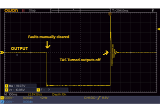
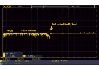
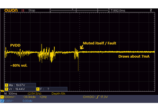
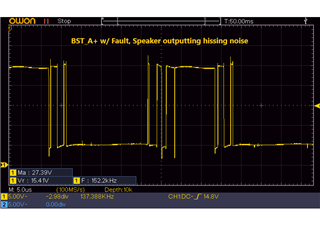
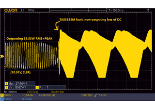
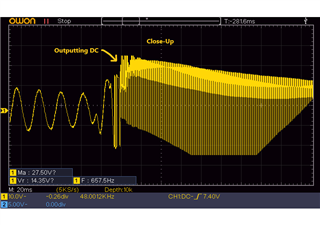
I'm having some trouble while prototyping with the TAS5825M. When playing at normal volumes everything works as expected, but when the volume is increased above ~80% it instantly mutes or sends huge amounts of voltage through my speaker. I've noticed this can happen more when PVDD is higher than about 16V.

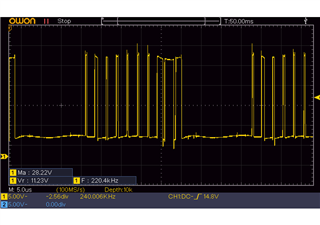
When this happens it shows different faults each time, alternating between;

CH1-DC=1 // CH1-OC=1 // CLK-Fault-i=1 // Or it shows no faults but sends about 10-80% of the supply voltage to the speakers.

-

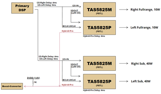
My setup is as follows:

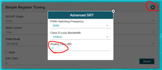
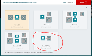
TAS5825M is in Mono-Mode (PBTL), 384KHz fs, PVDD is supplied with 18V (20V max), DVDD is 1.8V, driving 2.6Ohm. I'm trying to reach about 40W RMS.

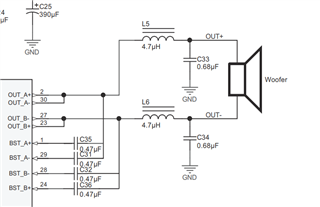
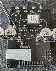
-Bootstrap caps: 470nF

-Bulk Caps (PVDD): 3x 220uF Low-ESR.

-Ceramic Caps (PVDD): 4x 4.7uF, + 2x 1uF, + 2x 100nF (Placed close to IC)

-Inductor: 10uH (PN: HA4158-EL) + 0.68uF

everything else is as datasheet suggests.

-

What could be the cause of this? Any advice is greatly appreciated:) 

Thanks!

  • Hello Diederik,

    Can you provide the following:

    • schematic
    • what loop bandwidth are you using
    • an oscope waveform of your Outputs, BST, and PVDD
    • your init sequence

    best regards,
    Luis

  • Hi Luis:)

    Thanks for your reply.

    -

    Sadly I'm unable to provide schematic since this has been lost. But it is the same as the datasheet suggests for PBTL, except previously mentioned specs.

    -

    I'm using a Loop-Bandwidth of 100KHz.

    -

    I will send waveforms later, are there any requirements as of what should be played on the TAS5825M while taking these readings?

    -

    Everything is purely set-up using the PurePathConsole-3. All system rails are active before connecting and writing all configs.

    --

    Thank!

  • Hello Diederek,

    Can you attach your PPC3 config.

    The waveforms can you provide them on startup and then before your fault condition>

    best regards,
    Luis

  • Hi Luis:)

    Thanks for your reply.

    -

    I've attached my PPC3 file. note that PBTL needs to be manually set-up in the registers.

    TAS5825M-Evaluation-V2.rar

    -

    Waveforms are taken with TAS5825M at 19V PVDD, 1.80V DVDD, 2.6Ohm Load, 384KHz, 80KHz BandWidth and 80% volume.

    -

    This wavefrom shows the output to the speakers when a DC fault occurs.

    Faults where manually cleared by setting address 0x78 to 0x80. TAS auto-muted itself short after as shown.

    -

    This wavefrom shows PVDD voltage before/after TAS mutes itself, and no faults are given.

    This is the same when a DC fault occurs. the 2 waveforms are 2 different scenarios.

    -

    This wavefrom shows the BST_A+ when in idle. No music is playing.

    -

    This wavefrom shows the BST_A+ when a fault is present, hissing noise is coming from the speaker.

    BST_B+ shows the same.

    -

    This wavefrom shows the BST_B- when a fault is present, speaker is getting small amount of DC w/ hissing.

    BST_A- shows the same.

    -

    Note: I later added a additional 220uF and 2x 10uF ceramic caps, but results did not change.

    -

    Hope this helps:)

  • hi, Diederik

    according your ppc3, if your pvdd is 19v, it would be better to config 20log(19/29.5) dB in AGAIN.

    also, the Isat of inductor is around 6A, it is too less for your SA might drive speaker to a higher power which having large current.

    using 6Ax1.4=8-9A would be better.

    tks

    jesse

  • Hi Jesse:)

    Thanks for your reply.

    -

    it would be better to config 20log(19/29.5) dB in AGAIN.

    I assume in PPC3 this is set in: Characterization > SOA/System-Gain? If yes, I did already try setting this at 29.5 and 20.9 as these values where used in the datasheet, this did not change anything however..

    -

    Isat of inductor is around 6A, it is too less

    I see, but since I was originally using the TAS5766M with the same 2.6Ohm drivers and HA4158-EL up to 50W RMS, How come the TAS5825M needs a higher Isat? - Would the GA3416-CL be a better choice instead?

    -

    Also, Why would this cause the amplifier to output DC voltage to the speakers? That seems like a huge design flaw with the TAS5825M itself if normal.

    When such a DC fault happens, it looks like the main system has crashed/jammed since no communication is possible, even pulling PDN low won't shut it off. This may be causing the FET-Drivers to be stuck in the last state, which might also explain why it outputs only a small amount of DC and sometimes huge amounts.

    -

    Thanks!

  • Hi Diederik

    #1

    you can set AGAIN as below:


    #2 yes, GA3416-CL is much better.

    you have same config with tas5766 like gain, EQ and volume.

    according to the gain setting, you output might haven't go that high (50w rms) when using tas5766 so that low Isat inductor also can work.

    also, 50w, 2.6ohm -> current is around 6.2A. if using 6A Isat inductor, which means inductor value will decrease a lot when 50w output.

    smaller inductor will lead to larger ripple current which lead to peak current go more than 6A.

    so even tas5766 can be ok with 6A isat inductor, it sill have risk which might lead to OC trigger.

    #3 if config normally, no DC should be able to be outputted.

    -> i found that you config PBTL manually, it is not a correct method.

    please select as flow to re-config your parameter, we have dedicated process flow for PBTL config.

    -> for you don't have the schematic, can you simply draw how you connecting the output for PBTL output.

    tks

    jesse

  • Hi Jesse:)

    Thanks for your reply.

    -

    you can set AGAIN as below

    I cannot set this parameter to 19/29.5dB, range is limited from 0dB to -15.5dB.

    -

    50w, 2.6ohm -> current is around 6.2A

    I see, What calculation is used for this?

    I tried limiting the TAS5825M to ~40W Peak which should be well below the 6A Isat from my inductor used, so technically it should not output any faults. But unfortunately, the behavior still consists.

    Output was measured at 10.01V max Peak which translates to about 38.53W at 2.6Ohm. In reality my speaker measures about 2.76Ohm so that translates to about 36.30W.

    Waveform can be seen here. PVDD is 19V with specs earlier mentioned. Waveform shows output at speaker.

    Close-Up:

    -

    if config normally, no DC should be able to be outputted.

    So when prototyping with TAS5825, which includes finding the right configs for specific applications, it is expected to run into this DC fault if wattage is set too high? 

    -

    i found that you config PBTL manually, it is not a correct method.

    Yes I am aware of this. However I need stereo processing for my SDOUT configuration. As far as I've tested the Mono-Process-Flow does not support this.

    I have tried both the Stereo and Mono Process-Flows but it does not effect the strange behavior.

    -

    can you simply draw how you connecting the output for PBTL output

    It is the same as you show, only difference is that instead of 4.7uH, I use 10uH ( HA4158-EL)

    -

    Also, is there any recommendation for what size bulk capacitors I should use for 2x50W/2.6R Peak + 2x12W/4R Peak (4x PBTL TAS)? Or maybe a way to calculate this?

    -

    Thanks!

  • hi diederik

    i suspect that your initial code seems having problem.

    do you have ppc3 file which can share to me ?

    or we can take a try below solution to help us check HW problem or SW problem.

    1. PBTL initial code.

    /cfs-file/__key/communityserver-discussions-components-files/6/5828_5F00_initial_5F00_code.cfg

    2. stereo 2.0 + manually set PBTL

     /cfs-file/__key/communityserver-discussions-components-files/6/5828_5F00_initial_5F00_code_5F00_2.0.cfg

    3. about how to config Again, please refer below file.

    https://www.ti.com/lit/an/slaa894/slaa894.pdf?ts=1688100995026&ref_url=https%253A%252F%252Fwww.ti.com%252Fproduct%252FTAS5805M%253FkeyMatch%253DTAS5805M%2526tisearch%253Dsearch-everything%2526usecase%253DGPN-ALT

    tks

    jesse

  • Hi Jesse:)

    Thanks for your reply.

    -

    Here are the updated PPC3 files (Stereo+Mono) with headerfiles;

    TAS5825M PPC3 w HeaderFiles.rar

    -

    I will try these codes next week. Thank you very much for all the help so far, it is really appreciated:)

    -

    Ah okay it is clear now how to set Again, thanks:)

    -

    Regards

  • Hi:)

    -

    The codes you send seem to be for TAS5828M, not TAS5825M.

    I tried them anyways by changing the address from 0xC0 to 0x98 for TAS5825M, but this did not work unfortunately.
    -

    Regards

  • Hi Jesse:)

    Thanks for your reply.

    -

    No worries, these new codes worked:)

    -

    What I found with the code for stereo is that the amplifier now does reach full volume without ever creating faults, however the output is very distorted at high volumes which seems to be caused by some heavy limiting/compression. This also causes a limited output of about 20W at 20V PVDD.
    -
    With the code for PBTL, nothing seems to have changed..

    -

    Something I did find is that when I enable the Dynamic-Range-Compressor (DRC) and limit higher bass peaks (attack <10ms) I can push the output a bit further, however the same DC faults still appear at higher levels.

    Btw, lowering the 'Again' also does not seem to improve anything.

    -

    Hope this helps:)

  • Hi Diederik

    can you share me your modification to the code?

    especially, the configuration of DRC and AGAIN.

    BTW, let me double confirm several parameter.

    PVDD: 20v max

    output peak power: 40w RMS

    load resistance : 2.6ohm

    PBTL mode.

    am i understanding correct?

    tks

    jesse

  • Hi Jesse:)

    Thanks for your reply.

    -

    The codes you send where not modified, I tried the 'Again' and 'DRC' in my original PPC3 file: TAS5825M-Evaluation-Mono.rar
    'Again' was tested from -4dB to -6dB. I also lowered input gain by 12dB and increased output by 12db since this should increase headroom (Tuning Guide page9).

    -

    Yes those specs are correct:)

    -

    Thanks!

  • Hi Diederik

    Base on your ppc3 file, i modified the setting and transform that to the script.

    can you take a try the script.

    /cfs-file/__key/communityserver-discussions-components-files/6/TAS5825M_2D00_Evaluation_2D00_Mono_2D00_aj.zip

    the smart amp be used, it enhanced the low frequency a lot which means your DRC suppression might has no effect to the output for the smart amp model is after the DRC.

    tks

    jesse

  • Hi Jesse:)

    Thanks for your reply.

    -

    With the Code uploaded via "Direct i2C" the output seems to be heavily limited again to about 5W. However this time the output does not seem distorted like the previous Stereo code at maximum volume.

    -

    As for the PPC3 file/project, results are the same. I tried increasing 'Again' from -6dB to 0dB and this increased output to about 10W without faults, but this is obviously far too little for my application.

    I also noticed that Automatic Gain Limiter (AGL) was enabled, this cannot be done in my final design as i will be using the TAS5825M with the TAS5825P for the Hybrid-Pro function, hence why I also needed the Stereo Process-Flow.

    I tried adjusting the PPC3 file to reach about 40W again by increasing "DAC-Gain" to 9dB+, but now it seems faults appear even faster, failing at about 20W.

    Only "DAC-Gain" was adjusted, everything else is left untouched.

    -

    I will try and replace the TAS5825M IC later, just in case the IC itself is faulty.

    -

    Thanks!

  • Also, maybe a bit off-topic, but is it possible to get a sample of the TAS5825MEVM for further prototyping?

    I assume the PurePath-CMBEVM is also needed for this, but it seems basic prototyping can be done for the TAS5825MEVM via the available Test-Pins as well.

    -

    Thanks!

  • Hi Diederik

    you should be able to apply EVM board from below link.

    https://tisamples.ti.com/order/tisamples/zh/

     this cannot be done in my final design as i will be using the TAS5825M with the TAS5825P for the Hybrid-Pro function, hence why I also needed the Stereo Process-Flow.

    -> about this issue, i am not very understanding your meaning.

    you mean you will use tas5825m generating the script and put it in tas5825p?

    if yes, i am afraid that you need to close smart amp for tas5825p doesn't have that function.

    you can use tas5825p model to generate the corresponding script.

    about why output is so small is because you have so large suppression in your EQ. 

    -20dB suppression is rare, can you tell me why?

    tks

    jesse

  • Hi Jesse:)

    Thanks for your reply.

    -

    Okay thanks, will do.

    -

    No I will both be using the TAS5825M and TAS5825P. Where the TAS5825M will do the main processing, and the TAS5825P will only be used for the Hybrid-Pro feature.  

    The TAS5825M will be processing both Left and Right Channels, but will only be outputting the Right channel itself, the Left-Channel will be send to the TAS5825P using the SDOUT.

    The Stereo Process-Flow is needed to add the same delay to the TAS5825M (Right-Channel) as is created by the TAS5825P (Left-Channel) with the Hybrid-Pro feature. This ensures proper operation without clipping/distortion and phase issues.

    Here is a diagram to clarify:

    -

    The large -21dB Treble-Shelf EQ is done because I am mainly testing with real speaker drivers and I don't want to annoy my neighbors. The Bass (<120Hz) is still pretty much untouched for output power measuring. In my end application the 40W Subwoofers will have a LowPass of about 500Hz anyways.

    -

    As for my prototype, I replaced the TAS5825M IC with a new one, along with new 470nF Bootstrap caps, new 100nF decoupling caps, shortened the path from the TAS5825M outputs to the inductor (PN: HA4158-EL) and now use a different speaker driver (same PN still) just in case my original one was somehow faulty. Unfortunately this made no difference, and I am now at a loss as to what the problem could be.

    The prototype at this stage:

    PVDD Caps: 4x220uF + 4x22uF + 2x 100nF.

    -

    Thanks!

  • hi Diederik

    the AGL you don't want to use, is that because you don't want the tas5825m configuration affect the tas5825p output?

    if yes, i think you can config as below which will make sdout output the data haven't been processed by DSP.


    tks

    jesse