This thread has been locked.

If you have a related question, please click the "Ask a related question" button in the top right corner. The newly created question will be automatically linked to this question.

TPA3255: Fault Output Hi-Z

Part Number: TPA3255


Hello,

The datasheet for the TPA3255 states that the outputs will go into a Hi-Z state during Fault conditions. Based on Figure 26. it looks like the low side gate drive goes high, wouldn't this cause the outputs to pull down instead of going into hi-Z (Assuming NMOS halfbridge output). We are seeing leakage current into the output when in a fault condition and want to clarify if this behavior is expected.

Thanks.

  • Hi 

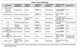
       The Figure 26 shows the CBC functions. The CBC threshold is smaller than OC. And from below table, you would see the CBC wouldn't make the output into Hi-Z, but try to limit the current as Figure 26 shows.

    We are seeing leakage current into the output when in a fault condition and want to clarify if this behavior is expected.

    Please make sure the real latched fault is being triggered, and the output is totally Hi-Z, before doing the test.

  • We are using Latched OC operation, we think the fault is due to uneven current draw in PBTL mode. The leakage is preventing the TPA from coming out of fault after reset. The only to fix is to fully disconnect outputs then reconnect. In fault, there is still a small common mode current on the pins due to other circuitry which is causing the current imbalance between the legs. Could this be causing the issue?

    Thanks.

  • Hi 

    The leakage is preventing the TPA from coming out of fault after reset. The only to fix is to fully disconnect outputs then reconnect.

    This behavior doesn't seems correct. 

    Could you please be more specific about how do you triggered the latched OC protection, and after the OC triggered, what is the voltage and leakage current you test out on each of the OUTPUT legs. And before we trying to reset, is all the fault condition been removed?

    We'd be appreciate if you could show us some waveform about your testing procedure, using oscilloscope to capture the output voltage or current. They would help us to analysis, thank you.