This thread has been locked.

If you have a related question, please click the "Ask a related question" button in the top right corner. The newly created question will be automatically linked to this question.

TLV320ADC5140: TLV320ADC5140 - Stereo PDM microphones over I2S

Part Number: TLV320ADC5140


I'm struggling to understand how I need to configure the TLV320ADC5140 to take two PDM microphones (hardware-configured for left and right) on a single TLV320 channel and send the data via I2S.

Whatever configuration I try seems to always end up with only the right microphone data being received at my microcontroller (an ESP32) and the audio is always jittery.

I'm absolutely certain it's my understanding of how I need to configure the TLV320ADC5140 and would appreciate some pointers.

So far, I followed the 8-channel PDM example in the datasheet however, I've stripped it back by removing 6 of those channels:

/* ASI_CFG0: I2S mode and 32bit word length */
0x07: 112 [0111 0000]
/* PDMIN_CFG: PDMDIN1_EDGE ch1 positive, ch2 negative respective of INMP621 datasheet, page 5 */
0x20: 192 [1100 0000]
/* GPO1_CFG: PDM clock output, drive active low active high */
0x22: 65 [0100 0001]
/* GPI_CFG0: PDM data input channel 1 and 2 */
0x2B: 69 [0100 0101]
/* CH1_CFG0: configured for PDM input */
0x3C: 64 [0100 0000]
/* IN_CH_EN: enable channel 1 */
0x73: 192 [1100 0000]
/* ASI_OUT_CH_EN: enable channel 1 slot */
0x74: 128 [1000 0000]

I guess I'm more confused about how both of the microphones on a single channel (with interleaved left/right data) maps to an output ASI slot. Does it still present as interleaved data over the I2S bus?

How is the frame size for the PDM interface determined? Is it 16-bits for left and 16-bits for the right channel, given that the ASI_WLEN is set to 32-bits?

Other relevant information:

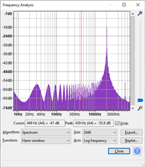
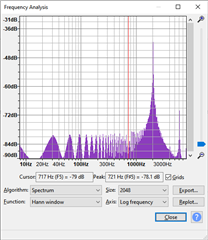
  • PDMCLK appears to be 3.072MHz
  • FSYNC is 16kHz
  • BCLK is 1.024MHz
  • Sample rate is 16kHz

I2S bus is initialised as follows:

Audio::Audio() :
  tlv {},
  bck {21},
  ws {25},
  data {27},
  sampleRate {16000},
  bitsPerSample {32},
  channelFormat {I2S_CHANNEL_FMT_RIGHT_LEFT},
  communicationFormat {I2S_COMM_FORMAT_I2S}
{
  /* zero the buffer */
  std::memset(this->buffer, 0, BufferSize);

  /* i2s configuration */
  this->config = {
    .mode = (i2s_mode_t)(I2S_MODE_MASTER | I2S_MODE_RX),
    .sample_rate = this->sampleRate,
    .bits_per_sample = i2s_bits_per_sample_t(this->bitsPerSample),
    .channel_format = this->channelFormat,
    .communication_format = this->communicationFormat,
    .intr_alloc_flags = ESP_INTR_FLAG_LEVEL1,
    .dma_buf_count = 4,
    .dma_buf_len = 1024,
    .use_apll = false,
    .tx_desc_auto_clear = false,
    .fixed_mclk = 0
  };

  /* configure the GPIO pins */
  this->pins = {
    .bck_io_num = this->bck,
    .ws_io_num = this->ws,
    .data_out_num = I2S_PIN_NO_CHANGE,
    .data_in_num = this->data
  };
}

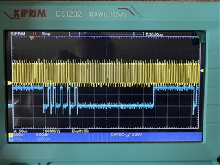
Below is a scope trace showing BCLK and SDOUT. It looks like only half the data is being sent on SDOUT:
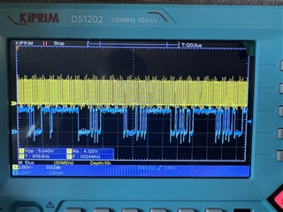
UPDATE:

I've updated ASI_CH1 = 32 so that it is I2S right slot 0 and I've set ASI_CH2 = 0 so that it is I2S left slot 0 and I now see more data on SDOUT:

Basically, I have absolutely no idea what I'm doing right now... 

  • If you use the exact configuration given in the datasheet with only 2 microphones ,do you see proper data?

  • Hello Sanjay,

    Thanks for your quick response.

    I shall check this very shortly. Unfortunately the output data format won't be compatible with my hardware as I don't believe the ESP32 supports TDM format (which is I believe what the datasheet example supports).

    I'm also struggling to understand how I can verify what "proper data" is - obviously I can see waveforms on the oscilloscope but this is not easy to interpret as good data. I did implement an audio frame transfer mechanism via USB which sent frames received over I2S to a Windows computer and played the frames out of the default audio playback device but these frames were very jittery and were very delayed so something was definitely wrong.

    I'll try the datasheet example again and update shortly.

  • Hi Sanjay,

    I've reverted everything back to the datasheet example for 8 channels, and only enabled 4 of them - GPO/GPI1 and GPO/GPI2 to which each of those channels has 2 PDM microphones attached. I have also only enabled 4 of the ASI channels in the ASI_OUT_CH_EN.

    I can confirm that there are gaps in the SDOUT data, as per my first oscilloscope trace.

    Here is a dump of the I2C registers:

    0x00: 0
    0x01: 0
    0x02: 129 [1000 0001]
    0x05: 5 [0000 0101]
    0x07: 112 [0111 0000]
    0x08: 0
    0x09: 0
    0x0B: 0
    0x0C: 1 [0000 0001]
    0x0D: 2 [0000 0010]
    0x0E: 3 [0000 0011]
    0x0F: 4 [0000 0100]
    0x10: 5 [0000 0101]
    0x11: 6 [0000 0110]
    0x12: 7 [0000 0111]
    0x13: 2 [0000 0010]
    0x14: 72 [0100 1000]
    0x15: 20 [0001 0100]
    0x16: 16 [0001 0000]
    0x1F: 64 [0100 0000]
    0x20: 0
    0x21: 34 [0010 0010]
    0x22: 65 [0100 0001]
    0x23: 65 [0100 0001]
    0x24: 0
    0x25: 0
    0x29: 0
    0x2A: 0
    0x2B: 69 [0100 0101]
    0x2C: 0
    0x2F: 0
    0x32: 0
    0x33: 255 [1111 1111]
    0x36: 192 [1100 0000]
    0x3B: 0
    0x3C: 64 [0100 0000]
    0x3D: 0
    0x3E: 201 [1100 1001]
    0x3F: 128 [1000 0000]
    0x40: 0
    0x41: 64 [0100 0000]
    0x42: 0
    0x43: 201 [1100 1001]
    0x44: 128 [1000 0000]
    0x45: 0
    0x46: 0
    0x47: 0
    0x48: 201 [1100 1001]
    0x49: 128 [1000 0000]
    0x4A: 0
    0x4B: 0
    0x4C: 0
    0x4D: 201 [1100 1001]
    0x4E: 128 [1000 0000]
    0x4F: 0
    0x52: 201 [1100 1001]
    0x53: 128 [1000 0000]
    0x54: 0
    0x57: 201 [1100 1001]
    0x58: 128 [1000 0000]
    0x59: 0
    0x5C: 201 [1100 1001]
    0x5D: 128 [1000 0000]
    0x5E: 0
    0x61: 201 [1100 1001]
    0x62: 128 [1000 0000]
    0x63: 0
    0x6B: 1 [0000 0001]
    0x6C: 64 [0100 0000]
    0x6D: 123 [0111 1011]
    0x70: 231 [1110 0111]
    0x73: 240 [1111 0000]
    0x74: 240 [1111 0000]
    0x75: 96 [0110 0000]
    0x76: 240 [1111 0000]
    0x77: 224 [1110 0000]
    0x7E: 40 [0010 1000]
    

    The only time I see what appears to be a normal waveform on SDOUT is when I swap the left/right slots round as per my update above.

  • Slightly more success now. I'm able to send received I2S audio frames via USB to my Windows software. As a test, I'm generating a 2kHz sine wave from my iPhone and listening to it via one of the channels. The resulting WAV file is attached - I'm not quite sure why it sounds like it does.

  • does I2S waveforms look ok?

  • As far as I can tell, the waveforms look ok

  • Hi Sanjay,

    Here are some spectrum plots of the WAV file which I've recorded directly from the I2S output:

    This first one has gain and volume applied to it. Note the dominant 2kHz frequency which is expected, however I am really not sure why there are other harmonics which are so prominent in the file. Could this be a configuration thing or could this now be an electrical thing - noise, etc? Given that the audio system is digital right the way through, I'm inclined to think it is more configuration or a framing issue but I could be wrong.

    This plot is when there is no gain or volume applied. Note that the same frequencies are present in the file:

  • pdm_xxx.cfg

    I have made a file using the Pure Path console tool for I2S output.I would suggest to use this tool. Would it be possible to try this file out with th below timing?

    LRCLK=48Khz

    BCLK=6.144 Mhz.

    Also, would you please describe your complete system so that i might understand the harmonics you see better