This thread has been locked.

If you have a related question, please click the "Ask a related question" button in the top right corner. The newly created question will be automatically linked to this question.

DRV2700EVM-HV500: PC4QM

Part Number: DRV2700EVM-HV500
Other Parts Discussed in Thread: DRV2700, DRV2700EVM

Hello,i have  a doubt, to use the DR 2700 EVM still with a ThorLabs device, but the 650nF PC4QM device , would it be possible? Has anyone worked with a combination of these devices and can report the experience? 

King regards.

  • Hello,

    Thank you for reaching out. I do not know of anyone who has worked with a similar load for this EVM, but am working on some calculations to see if this would work. As on now I can't find a similar load to try this out in the lab but will keep searching.

    Are you able to calculate the instantons current? Do you know what frequency you will be using?

    Regards,
    Sydney Northcutt 

  • Hi Sydney,

    Thanks for getting back to me. 

    Sorry for the delay in responding to you again, I'm from Brazil, and in recent days activities have been at a standstill due to the country's Independence celebrations.

    The frequency is around 240 - 250 Hz, and the PC4QM that I am working on operates with voltages of up to 150V, however for our application it is receiving a signal of approximately 5V.

    The maximum current (peak) is below 100mA.

  • Hi Bruno,

    No worries, thank you for providing the information. The DRV2700EVM-HV500 was not designed to go over 11mA. For your desired frequency and input voltage to the load the instantaneous load current is low, so I think the EVM could provide this. I wasn't able to find anything in the lab to test this type of load, so I can't comment on the performance. For your reference, figure 13 from the user guide is what I have been referring to.

    Regards,
    Sydney Northcutt

  • Hello Sydney
    
    
    Thank you for your help, it was enlightening.
    
    
    I will also do some computer simulations using Isis Proteus. Does the DRV have a model compatible with the software?
    
    Or would the parameters be available for inclusion?


    Thanks again.

    Regards.
  • Hi Bruno,

    We do not have a Proteus model, but we do have PSpice and TINA models which are on the DRV2700 product page. You can download PSpice or TINA on ti.com if you would like to simulate using one of those. 

    Regards,
    Sydney Northcutt

  • Hi Sydney,

    Thank you for all the clarifications so far, just to confirm my purchase request.

    For this application, considering the load I mentioned and the curves analyzed, I will order a DRV2700EVM-HV500 to work together on the project. If you confirm to me, as soon as I have the DRV here, I will carry out the tests, and return here to publish the results obtained.

    Regards.

  • Hi Bruno,

    Is there a reason you want the high voltage EVM specifically? I assumed you already had it on hand. Have you considered the DRV2700 EVM?

    Regards,
    Sydney Northcutt 

  • Yes, 

    Also considered were.

    For the application I mentioned with the Thorlabs PC4QM of 650nF, considering the 5V input signal. In your opinion, which would be more viable, the HV-500 or just the 27000EVM. 

    I thank.

     Regards.

  • Hi Bruno,

    I would recommend the DRV2700EVM considering you are only needing to supply 5V to your load. The DRV2700EVM-HV500 is mostly used when higher voltages are needed that the other EVM can not support. 

    Regards,
    Sydney Northcutt

  • Certo, 

    Obrigado mais uma vez Sidnei 

    Vou adquirir isso, realizar os testes necessários e voltar aqui com qualquer dúvida ou com a finalização dos testes.

    Cumprimentos.

  • Hi Bruno,

    Sounds good. I will close this thread for now. 

    Regards,
    Sydney Northcutt

  • Sydney, 

    Please,

    Just a matter of confirmation, as I did not find a curve in the DRV2700EVM documents, similar to the one you presented to me for the DRV2700EVM - HV500 model

    My application receives an input signal of 5V (limit) the typical input (Typical Volt) is close to 3.7V, which currently undergoes a 30x amplification, reaching approximately 111V.

    I opted for the DRV2700EVM, as it supports up to 200 V at the output, as long as my input voltage does not exceed 5.5V, did I make a mistake in this line of reasoning?

    Thank you again.

    Regards.

  • Hi Bruno, 

    Both EVMs have a supply voltage range of 3.6V - 5.5V and an input voltage range of 0V - supply voltage. Your are correct that the DRV2700EVM can support 200Vpp output, which fits your application. The DRV2700 data sheet has graphs which coordinate to the DRV2700EVM, specifically in section 6.7 Typical characteristics. I have added two plots below that I believe will be helpful. I also recommend looking at the boost load current graphs.

    Regards,
    Sydney Northcutt

  • Hi Sydney,

    How are you ?
    
    Please, the DRV arrived here at the laboratory, and when we connected it to the PC4QM load nothing happened.
    
    I am using a 5.5V DC source at the DRV's external input terminals, which I can measure 5.5V.
    
    The signal is entering the board through the analog input terminal, and is a 5V signal coming from the analog output of a NI 6009 DAC, which I also measure normally.
    
    I connected the 650nF PC4QM load to the OUT+ and OUT- terminals.
    
    Of the factory standard jumpers, I only changed JP11, switching the power from USB to external power.
    
    I emphasize that I did not connect it to the Piezo Controle software at any time.
    
    How can you help me ?
    
    Grateful.

  • Hi Bruno,

    Are you powering through USB as well as the external power supply? If not, you also need to change jumper JP10 to external power, which switches the supply route for the MSP430 on the board. The jumper JP11 only changes the power supply for the DRV2700. 

    Regards,
    Sydney Northcutt 

  • I am only feeding it via an external source, a 5.5V source, and a signal from the analog output of a DAC. I changed jumpers JP10 and JP11 to an external power supply, and the output still has no response.

  • Do I necessarily need to connect the DRV to a computer? To perform some first configuration? Or can I use this directly?
    
    The Jumper JP9 caused me some doubt as to the position I should keep it in, would it be the factory default?
  • Hi Bruno,

    I was thinking this EVM had capacitive touch capabilities, but it does not so you do need to connect to piezo console to control this EVM. If you are using an external analog input signal you would have to change JP9, otherwise you can leave JP9 in the default position (connected to MSP). 

    Regards,
    Sydney Northcutt

  • Yes, I am using an external signal, at the analog input there is the signal coming from the NI 6009 DAC. My JP9 is in EN and MSP, which one do I need to change to? In addition, do I need to change any other jumpers? Grateful.

  • Hi Bruno,

    Instructions on using an external analog input from the DRV2700EVM User Guide can be found below. 

    Regards,
    Sydney Northcutt

  • Sorry for my difficulty in understanding.
    
    I will remove Jumpers JP5 and JP6.
    
    Do I keep JP9 in the position I mentioned previously?
    
    Even if my input signal is not sinusoidal?
    
    Furthermore, what specifically do I need to configure through the software?
    
    Grateful.
  • Sydney,

    Good morning, I tried to do the steps you provided, but in item 8.2.3, it asks to change the resistors, and also remove the capacitors, for an analog input signal, but I was unable to find a way to make this change.

    Could you enlighten me? Because I still have 0V at the output of the OUT + and OUT- terminals.

    Grateful.

  • I just tried to connect the device to the computer.

    And on none of the company's computers

    I was able to get the device to connect to the Piezo Console V 1.2.9.0.

    The device is recognized but when trying to open the "console" part of the software, I receive the message "An unhandled exception has occurred in the application. If you click Continue, the application will ignore this error and attempt to continue. If you click Quit, the application will immediately exit."

    NOTE: To connect to the PC, I changed the jumpers that were in the VIN power position to USB again.

    I'm starting to believe that my DRV isn't working,

    I'm counting on support.

    Grateful.

  • I keep trying to work.
    
    Current situation :
    
    By pressing the SW1 button and connecting the USB I was able to connect the device to the software, I updated the firmware to version v1.7.
    
    Now he is normally recognized.
    
    I have measured the following output values:


    GND and OUT + : -12V
    
    GND and OUT - : 12V
    
    VBST and GND: 24V
    
    Jumpers JP2 JP3 and JP4 open.
    
    However, OUT + and OUT - if I measure between them, it still has a zero value.
    
    I tried to apply a dc signal coming from a 3V dc source to the analog input.
    
    However, I was not successful in amplifying these 3V.
  • Hello,

    From 5.3 I provided, EN refers to JP9, GAIN1 refers to JP8, and GAIN0 refers to JP7. These are the control signals for the DRV2700 device. You can use the software (which uses the MSP430) to control these signals or you can control them externally. 

    From 8.2.3, this is just for removing the filter as it may not be necessary for some input signals. This would be a soldering change / manually swapping out the components. 

    A DC signal does not go into the analog input, this is only for analog / sinusoidal signals. Section 5.4 in the User Guide provides the information to set up for single-ended input, depending on if you want to do set reference or floating reference. 

    When you says measure between OUT + and OUT -, are you measuring them differentially? Could you provide oscilloscope images?

    Also just a note, you do not have to have USB power when connecting to the software. You can still provide power via Vin and just use the USB to control the board. 

    Regards,
    Sydney Northcutt 

  • At the moment unfortunately I don't have an oscilloscope here.

    And we also don't have any signal to measure, since the device doesn't provide me with any response, it seems to be completely inoperative.

    I need to connect a DC input and feed via VIN, this is what I'm doing.

    I connected my PC4QM to the OUT+ and OUT- terminals, but nothing happens.

    Jumpers JP5 and JP6 have already been removed, what do I need to do to get it working?

    Through the Piezo Console I was able to connect it, but I can't make an output happen.

    Yes, I'm measuring with a multimeter between OUT+ and OUT- which is where I expect to see approximately 150V.

    I count on your support to make this architecture operate.

  • I can connect the GND of the DAC output to IN- and the 5V to DCIN, the orange terminal that I located on the board.

    As I said before, JP5 and JP6 are out.

    However, looking at item 5.4 I honestly can't understand how to do items 2 and 4, I lack clarity on how I'm going to carry out these actions.

  • I continue working with the information you gave me. At the moment my scenario:
    
    
    JP2,JP3,JP4,JP5,JP6 Open
    
    Power via external, the two power jumpers for Vin
    
    JP7 in MSP and GAIN0
    
    JP8 in GAIN1 and MSP
    JP9 in EN and MSP
    
    
    DC 5V signal from DAC connected to DCIN ( Orange conector)
    
    DAC 5V GND connected to TP8
    
    I continue measuring from a multimeter 0V between OUT+ and OUT-
  • Update : 

    Measuring between DCIN and TP7 or between DCIN and TP8 with a multimeter, I find 2.44V DC.
    
    I tried applying voltage levels from a DC source directly to DCIN, such as 1.5V, 2V, 3V. without having a GND pin for this supply, directly the voltage at DCIN (Orange).
    
    Maintaining the Jumpers configuration that I passed previously
    
    And my OUT+ / OUT- output continues to indicate 0V on the multimeter.
    
    In fact I measure a noise/residue of 9mV
  • Hi Bruno,

    Yes no worries, we will get it working! For single ended input mode, you also need to jump JP13. This is what step 2 is referring to. For step 4, ground works for the DC reference on TP8. On the software, you will also need to select enable so that the DRV2700 device can output. 

    Regards,
    Sydney Northcutt

  • Thanks.
    
    Okay, I closed the jumper on JP13.
    
    I will apply the DC signal to DCIN and JP8.
    
    But in the software, can you tell me what I need to select?
    
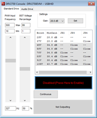
    The only configuration screen that I can recognize is the one I send you a screenshot of attached to this message.
    
    Grateful.
    Regards.

  • Hi Bruno,

    Where it says "Disabled (Press Here to Enable)", that is what you need to press to enable the DRV2700. The software is controlling gain0, gain1, and enable (this was set with jumpers JP7, JP8, and JP9), so you also want to set your gain in the GUI before enabling the output.

    Regards,
    Sydney Northcutt 

  • Hi Sydney,
    
    Thank you very much.
    
    I closed JP13,
    
    I enabled output via the Piezo Console.
    
    And with a multimeter I measured 22V between OUT +/ -.
    
    This gives you a small sign of operation.
    
    However, my Jumpers JP7, JP8, JP9 are
    
    
    In EN/MSP
    GAIN 1/MSP
    AND GAINO/MSP
    
    To get the 150V that we talked about before, I need to change these or jumpers JP2,JP3,JP4.
    
    In addition, one more question that came to me this morning, please.
    
    Now with the DRV connected to the computer, I enable the output, via the piezo console and I have output, but later with power from an external source, without connection to the USB/software, how do I enable the output?
    
    Grateful.
    
    I await your answers.
    
    Regards.
  • I keep working,

    Last voltage measurements with the multimeter maintaining the setup

    I gave you were as follows: With the jumpers for Boost 23V I measure 22V between OUT + / OUT -

    For 37V I measure 33V,

    Jumpers for 105V measured 99V.

    However, I understand that there is no real amplification of my DC input signal,

    I only measure the Boost, when my DC signal reaches voltage levels close to 1.9V 2.0V Am

    I on the right path to make this work?

    Regarding the JP 7,8,9 Jumpers, should I keep them in those positions I gave you?

    These are the factory defaults.

    Grateful.

    Regards.

  • Hi Bruno,

    I have been working on getting the DRV2700EVM in hand so I can take some measurements myself and help you get the desired output. I hope to get it before the end of the week. For JP2, JP3, and JP4, I believe you have these all shorted to achieve the 105V boost, this is the right path. For jumpers JP7, JP8, and JP9, you currently have them set to MSP, which means you are controlling these signals via the software. The software communicates with the MSP430 controller on the board via USB. The MSP430 then sends the data to the DRV2700 digital control pins which allows it to operate. In production, instead of the software you would have some other interface that goes to a controller which will then send digital controls the DRV2700. The other interface could be a button press or communication with another device. 

    Regards,
    Sydney Northcutt 

  • Hi Sydney,
    
    My final application, what I will need to change from the current scenario we are working on.
    
    I need to power it via an external source instead of USB.
    
    And my external signal, which currently comes from a common external bench source, will now be from the analog output of a DAC 6009.
    
    At the moment, at the OUT +/- output, I apparently only measure the boost value that I select in the software, even though I have nothing at the DCIN and JP8 inputs.
    
    I recently did a test leaving there no voltage level at DCIN and JP8 and measured VBST at OUT +/-
    
    Which makes me believe that my input signal is being useless in this scenario, I need to be able to inject the DAC signal into some terminal, be it DCIN and TP8 or somewhere else, and amplify it obtaining something close to 100V.
    
    This is my intention with this device.
    
    I continue to count on your help.
    
    Regards.
  • In summary,
    
    What I want to get as working in drv is
    
    
    Power it from an external source
    
    Inject an analog level from the DAC 6009, and have this voltage value multiplied (gain applied) to an output terminal, to which I can connect my PC4QM (650nF) and thus obtain the movement of this piezo device.
    
    
    I am working to obtain this result.


    Regards.
  • Hi Bruno,

    Aren't you currently powering it via external source (Vin), not USB? Do you mean control it via an external source? On the board you can supply external digital controls to the DRV2700 by removing and connecting to JP7, JP8, and JP9 or you can pull them all high with the jumpers. Once I get them EVM I can test why you are only measuring the boost on the output. 

    Regards,
    Sydney Northcutt 

  • Power is currently via USB. With jumpers JP10 and JP11 for USB.
    
    I have a bench source connected to the DCIN and JP8 pins that I have injected 1.7V in my most recent tests.
    
    And I have measured OUT + / OUT- using a multimeter, my multimeter is a Minipa ET-2231, a reliable multimeter, with good precision.
    
    However, what I noticed is that regardless of whether or not there is a value being connected to DCIN and JP8, I am measuring VBST on the OUT+/OUT- terminals, which does not work for me.
    
    I need to be able to get 20, maybe 30 units of gain for my DC input signal, coming from the DAC.
    
    Regards.
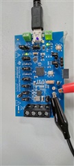
  • Perhaps a photo will help you understand how it is currently progressing.
    About position of jumpers and cables


    Regards.

  • Hi Bruno,

    Thanks for the detailed information. I was able to get the DRV2700EVM this morning. Will provide you with an update today.                                      

    Regards,
    Sydney Northcutt           

  • Thanks,

    I will wait.

    Regards.

  • Hi Bruno,

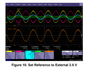
    After doing some testing, I found that when doing a purely DC signal, you can not get the full 200Vpp differential output and can only get about half. This is because the DC signal stays at a positive voltage difference from the reference voltage, so the amplifier can't produce the full differential output. When I did have the DC signal input and it was outputting around 115V DC differentially and then turned off the DC input signal, the differential output when to 0. I am not sure what you measured when you saw differently (turning off the DC input still giving a differential measurement). To achieve the differential output of 200Vpp, you have to have a positive and negative difference between the signal and reference voltage. I replicated these measurements today for a single ended input and believe this is something you might like to try.

    Supply IN- (TP8) with a DC signal. I did 2.5V. Supply IN+ (TP7) with a sine wave with a DC offset that is the same DC value as TP8. I did my sine wave at 250Hz as this is what you specified earlier in the tread. Ensure that J13 is not shorted and TP7 does not exceed 5V. If you do want it to exceed 5V you have to connect J13 and use DC_IN rather than TP7. In this case, be sure DC_IN does not go above 10V. 

    Regards,
    Sydney Northcutt 

  • Hi Sydney,
    
    Okay, I understand. Thanks.
    
    Could you please measure it in your laboratory and let me know.
    
    Using an external power supply (bench source) to supply power to the DRV.
    
    Inject a purely DC signal as an input signal to the DRV.
    
    What is the best jumper/connection configuration.
    
    And how much gain can I get? 20, 25 gain units.
    
    This would be paramount for me.
    
    Thank you very much again for your help.
    
    Regards.
  • Hi Bruno,

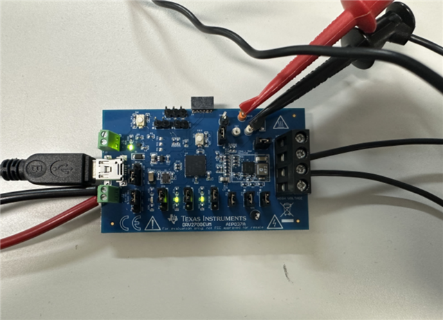
    Below is an image of the EVM with an external Vin supply and DC input signal to the DRV device. With an input and supply of 4.5, I got a DC output around 105V. 

    Regards,
    Sydney Northcutt

  • Hi Sydney,
    
    Thank you very much for your feedback, sorry for the delay in getting back to you.
    
    This is very similar to what I got here, using the DC input, and we connected to the same terminals, from what I can see, I believe the jumpers are in the same positions.
    
    I think this is the limit of work we can get with this device, right?
    
    And please Sydney, confirm for me, is it possible to work with it this way without connecting it to the software?
    
    If so, how would you go about enabling the output?
    
    Thanks again for all your support.
    
    An excellent week.
    
    Regards.
  • Hi Bruno,

    With a DC input, yes this is the max output we can get. Yes, you can use the EVM like this without connecting to the software. Right now, JP9, JP8, and JP7, are all tied to the I/O of the MSP430. That means you are controlling it with the software. You can use the jumpers to configure them how you want (high (connected to MSP power supply, or low (open)) or you can connect external controllers to the pins. 

    Regards,
    Sydney Northcutt

  • Good morning Sydney,
    
    Okay, please
    
    Please confirm for use without the software, directly with the external source to connect the driver, and enable the output, do I leave the jumper in the PU position?
    
    Grateful.
    
    Regards.
  • Hi Bruno,

    If you put those jumpers in the PU (pull up) position, they will be high. For the enable pin JP9, that means the output will always be enabled unless you remove the jumper. Same goes for JP8 and JP7. You will need to have them configured for the gain you want. For the highest gain, position both jumpers (JP8 and JP9) to the PU position. 

    Regards,
    Sydney Northcutt