This thread has been locked.

If you have a related question, please click the "Ask a related question" button in the top right corner. The newly created question will be automatically linked to this question.

PCM5122: output signals not in phase between different PCM5122

Part Number: PCM5122
Other Parts Discussed in Thread: PCM1680, PCM4104, PCM1690, PCM5121

Dear,

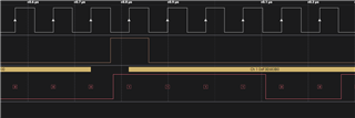
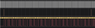
We using the PCM5122 4 times on a TDM bus of 48KHz 32bit audio samples.
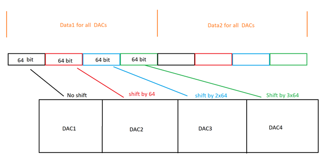
Each DAC has the same configuration, registers are identical except shift register 41.

The I2S Shift registers for DAC 1 = 0
The I2S Shift registers for DAC 2 = 64
The I2S Shift registers for DAC 3 = 128
The I2S Shift registers for DAC 4 = 192

On the TDM bus has each slot (8 in total) of each frame the same values.
So each output must have the same signal.

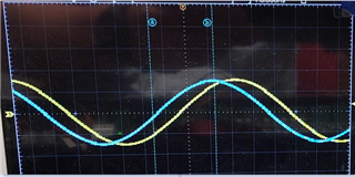
For each DAC are the Left and right channels in phase
For DAC2, DAC3, DAC 4 are all the channels in phase.
But not for DAC1 and all the other DAC/channels.

It is only when we set in the phase register 41 the value 0 that the output signals are not more in sync.
The different is 1 LRCLK.

So we cannot understand that only our DAC1 isn't in phase with the other channels.
How we can resolve this issue?


  • Few things you need to check and see if you can isolate the issue to be one specific DAC in the array or one specific location in the array.

    Have you tried to reverse the order of DACs and see the effect. For example you are sending the data in this order to DAC1, DAC2, DAC3 and DAC4, what happens if you send the data in the following order DAC4, DAC3, DAC2 and DAC1 using register 41 modification.

    Case 1) If you see the same problem with first DAC ( which  is DAC4 in this new case) then your registers are okay and you have to figure out the issue in sending the data as it might not be what you think it is. Equivalently, I think you can send the data to DAC2 and DAc3 and DAC4 only and  leave a blank  placeholder for the last DAC and see if the problem moves to DAC2 which is now the first DAC in the array.

    Case 2) If you still see the problem with the same DAC  that is now placed as the last DAC in the chain, then it  can be the settings of that specific DAC.

    Few "possible"  registers to check: 

    • Note in page 9, the DAC can have different delay /latency based on programmed filter- ( this is not likely the case as for 48k sampling rate, delay is proportional to N*20ns , nevertheless confirm the settings are the same.
    • Register 9 , bit BCKP that sets the BCK to be inverted or not (wrt data and LRCLK edges)
    • Register 40,  bits  AFMT[1:0]   that set TDM, LJ, I2S, RJ and ....

    I think the above should get you going in the right  direction .  Let me know if you have any questions after Thursday as I will be out of office until then.

    Regards,

    Arash

  • Dear,

    Case1 ==> We have try it and the results are the same.
                       We had tried other orders of DACs and it is the DAC with offset 0 that has the correct signal and the other DAC is the signal 1 LRCLK later.

    Case2: ==> If we good understand this test, we must use on offset of 0 for DAC 2, 64 for DAC 3 and 128 for DAC4 and DAC1 is disabled.
                        the result is that DAC 2 has the correct signal and other DAC are 1 LRCLK later.
                        Also made other tests, but the conclusion is that the issue has nothing to do with the shift offset register. (impossible to create a phase shift with the shift register) 

    See also the register dumps of DAC 0 and DAC 1

    • Note in page 9, the DAC can have different delay /latency based on programmed filter- ( this is not likely the case as for 48k sampling rate, delay is proportional to N*20ns , nevertheless confirm the settings are the same.
      ==> Every register in each DAC are identical, has checked with a register dump on each DAC (except the offset register is different)
      ==> We don't use this filters and if we use it it should be giving the same results on each DAC

    • Register 9 , bit BCKP that sets the BCK to be inverted or not (wrt data and LRCLK edges)
      ==> Has the correct settings. also tried to invers this bit, but with the same phase shift results (but incorrect signal)

    • Register 40,  bits  AFMT[1:0]   that set TDM, LJ, I2S, RJ and ....    
      ==> Has the correct settings  (AFMT[1:0]  = 01: TDM/DSP / ALEN[1:0] = 11: 32 bits)

    btw: we had also connect the TDM bus of the DAC on an audio analyzer (audio precession) and then we become the correct results.
    So what goes wrong?

     INFO - ******** DUMP PCM512X Registers for device: 0 *******
     INFO - ******** Page   0 ********
     INFO - ePCM512X_RESET             = 0x00
     INFO - ePCM512X_POWER             = 0x00
     INFO - ePCM512X_MUTE              = 0x00
     INFO - ePCM512X_PLL_EN            = 0x10
     INFO - ePCM512X_SPI_MISO_FUNCTION = 0x00
     INFO - ePCM512X_DSP               = 0x00
     INFO - ePCM512X_GPIO_EN           = 0x1e
     INFO - ePCM512X_BCLK_LRCLK_CFG    = 0x00
     INFO - ePCM512X_DSP_GPIO_INPUT    = 0x00
     INFO - ePCM512X_MASTER_MODE       = 0x7c
     INFO - ePCM512X_PLL_REF           = 0x00
     INFO - ePCM512X_DAC_REF           = 0x30
     INFO - ePCM512X_GPIO_DACIN        = 0x00
     INFO - ePCM512X_GPIO_PLLIN        = 0x00
     INFO - ePCM512X_SYNCHRONIZE       = 0x10
     INFO - ePCM512X_PLL_COEFF_0       = 0x00
     INFO - ePCM512X_PLL_COEFF_1       = 0x00
     INFO - ePCM512X_PLL_COEFF_2       = 0x00
     INFO - ePCM512X_PLL_COEFF_3       = 0x00
     INFO - ePCM512X_PLL_COEFF_4       = 0x00
     INFO - ePCM512X_DSP_CLKDIV        = 0x00
     INFO - ePCM512X_DAC_CLKDIV        = 0x00
     INFO - ePCM512X_NCP_CLKDIV        = 0x00
     INFO - ePCM512X_OSR_CLKDIV        = 0x00
     INFO - ePCM512X_MASTER_CLKDIV_1   = 0x00
     INFO - ePCM512X_MASTER_CLKDIV_2   = 0x00
     INFO - ePCM512X_FS_SPEED_MODE     = 0x00
     INFO - ePCM512X_IDAC_1            = 0x01
     INFO - ePCM512X_IDAC_2            = 0x00
     INFO - ePCM512X_ERROR_DETECT      = 0x01
     INFO - ePCM512X_I2S_1             = 0x13
     INFO - ePCM512X_I2S_SHIFTS        = 0x00
     INFO - ePCM512X_DAC_ROUTING       = 0x11
     INFO - ePCM512X_DSP_PROGRAM       = 0x01
     INFO - ePCM512X_CLKDET            = 0x00
     INFO - ePCM512X_AUTO_MUTE         = 0x00
     INFO - ePCM512X_DIGITAL_VOLUME_1  = 0x00
     INFO - ePCM512X_DIGITAL_VOLUME_2  = 0x30
     INFO - ePCM512X_DIGITAL_VOLUME_3  = 0x30
     INFO - ePCM512X_DIGITAL_MUTE_1    = 0x22
     INFO - ePCM512X_DIGITAL_MUTE_2    = 0x02
     INFO - ePCM512X_DIGITAL_MUTE_3    = 0x03
     INFO - ePCM512X_GPIO_OUTPUT_1     = 0x00
     INFO - ePCM512X_GPIO_OUTPUT_2     = 0x02
     INFO - ePCM512X_GPIO_OUTPUT_3     = 0x02
     INFO - ePCM512X_GPIO_OUTPUT_4     = 0x02
     INFO - ePCM512X_GPIO_OUTPUT_5     = 0x02
     INFO - ePCM512X_GPIO_OUTPUT_6     = 0x00
     INFO - ePCM512X_GPIO_CONTROL_1    = 0x00
     INFO - ePCM512X_GPIO_CONTROL_2    = 0x00
     INFO - ePCM512X_OVERFLOW          = 0x00
     INFO - ePCM512X_RATE_DET_1        = 0x36
     INFO - ePCM512X_RATE_DET_2        = 0x01
     INFO - ePCM512X_RATE_DET_3        = 0x00
     INFO - ePCM512X_RATE_DET_4        = 0x20
     INFO - ePCM512X_CLOCK_STATUS      = 0x00
     INFO - ePCM512X_ANALOG_MUTE_DET   = 0x33
     INFO - ePCM512X_PWR_STATUS        = 0x85
     INFO - ePCM512X_GPIN              = 0x01
     INFO - ePCM512X_DIGITAL_MUTE_DET  = 0x00
     INFO - ******** Page   1 ********
     INFO - ePCM512X_OUTPUT_AMPLITUDE  = 0x00
     INFO - ePCM512X_ANALOG_GAIN_CTRL  = 0x11
     INFO - ePCM512X_UNDERVOLTAGE_PROT = 0x00
     INFO - ePCM512X_ANALOG_MUTE_CTRL  = 0x00
     INFO - ePCM512X_ANALOG_GAIN_BOOST = 0x00
     INFO - ePCM512X_VCOM_CTRL_1       = 0x00
     INFO - ePCM512X_VCOM_CTRL_2       = 0x01
     INFO - ******** Page  44 ********
     INFO - ePCM512X_CRAM_CTRL        = 0x00
     INFO - ******** Page 253 ********
     INFO - ePCM512X_FLEX_A           = 0x00
     INFO - ePCM512X_FLEX_B           = 0x00
    INFO - ******** DUMP PCM512X Registers for device: 1********
     INFO - ******** Page   0 ********
     INFO - ePCM512X_RESET             = 0x00
     INFO - ePCM512X_POWER             = 0x00
     INFO - ePCM512X_MUTE              = 0x00
     INFO - ePCM512X_PLL_EN            = 0x10
     INFO - ePCM512X_SPI_MISO_FUNCTION = 0x00
     INFO - ePCM512X_DSP               = 0x00
     INFO - ePCM512X_GPIO_EN           = 0x1e
     INFO - ePCM512X_BCLK_LRCLK_CFG    = 0x00
     INFO - ePCM512X_DSP_GPIO_INPUT    = 0x00
     INFO - ePCM512X_MASTER_MODE       = 0x7c
     INFO - ePCM512X_PLL_REF           = 0x00
     INFO - ePCM512X_DAC_REF           = 0x30
     INFO - ePCM512X_GPIO_DACIN        = 0x00
     INFO - ePCM512X_GPIO_PLLIN        = 0x00
     INFO - ePCM512X_SYNCHRONIZE       = 0x10
     INFO - ePCM512X_PLL_COEFF_0       = 0x00
     INFO - ePCM512X_PLL_COEFF_1       = 0x00
     INFO - ePCM512X_PLL_COEFF_2       = 0x00
     INFO - ePCM512X_PLL_COEFF_3       = 0x00
     INFO - ePCM512X_PLL_COEFF_4       = 0x00
     INFO - ePCM512X_DSP_CLKDIV        = 0x00
     INFO - ePCM512X_DAC_CLKDIV        = 0x00
     INFO - ePCM512X_NCP_CLKDIV        = 0x00
     INFO - ePCM512X_OSR_CLKDIV        = 0x00
     INFO - ePCM512X_MASTER_CLKDIV_1   = 0x00
     INFO - ePCM512X_MASTER_CLKDIV_2   = 0x00
     INFO - ePCM512X_FS_SPEED_MODE     = 0x00
     INFO - ePCM512X_IDAC_1            = 0x01
     INFO - ePCM512X_IDAC_2            = 0x00
     INFO - ePCM512X_ERROR_DETECT      = 0x01
     INFO - ePCM512X_I2S_1             = 0x13
     INFO - ePCM512X_I2S_SHIFTS        = 0x40
     INFO - ePCM512X_DAC_ROUTING       = 0x11
     INFO - ePCM512X_DSP_PROGRAM       = 0x01
     INFO - ePCM512X_CLKDET            = 0x00
     INFO - ePCM512X_AUTO_MUTE         = 0x00
     INFO - ePCM512X_DIGITAL_VOLUME_1  = 0x00
     INFO - ePCM512X_DIGITAL_VOLUME_2  = 0x30
     INFO - ePCM512X_DIGITAL_VOLUME_3  = 0x30
     INFO - ePCM512X_DIGITAL_MUTE_1    = 0x22
     INFO - ePCM512X_DIGITAL_MUTE_2    = 0x02
     INFO - ePCM512X_DIGITAL_MUTE_3    = 0x03
     INFO - ePCM512X_GPIO_OUTPUT_1     = 0x00
     INFO - ePCM512X_GPIO_OUTPUT_2     = 0x02
     INFO - ePCM512X_GPIO_OUTPUT_3     = 0x02
     INFO - ePCM512X_GPIO_OUTPUT_4     = 0x02
     INFO - ePCM512X_GPIO_OUTPUT_5     = 0x02
     INFO - ePCM512X_GPIO_OUTPUT_6     = 0x00
     INFO - ePCM512X_GPIO_CONTROL_1    = 0x00
     INFO - ePCM512X_GPIO_CONTROL_2    = 0x00
     INFO - ePCM512X_OVERFLOW          = 0x00
     INFO - ePCM512X_RATE_DET_1        = 0x36
     INFO - ePCM512X_RATE_DET_2        = 0x01
     INFO - ePCM512X_RATE_DET_3        = 0x00
     INFO - ePCM512X_RATE_DET_4        = 0x20
     INFO - ePCM512X_CLOCK_STATUS      = 0x00
     INFO - ePCM512X_ANALOG_MUTE_DET   = 0x33
     INFO - ePCM512X_PWR_STATUS        = 0x85
     INFO - ePCM512X_GPIN              = 0x01
     INFO - ePCM512X_DIGITAL_MUTE_DET  = 0x00
     INFO - ******** Page   1 ********
     INFO - ePCM512X_OUTPUT_AMPLITUDE  = 0x00
     INFO - ePCM512X_ANALOG_GAIN_CTRL  = 0x11
     INFO - ePCM512X_UNDERVOLTAGE_PROT = 0x00
     INFO - ePCM512X_ANALOG_MUTE_CTRL  = 0x00
     INFO - ePCM512X_ANALOG_GAIN_BOOST = 0x00
     INFO - ePCM512X_VCOM_CTRL_1       = 0x00
     INFO - ePCM512X_VCOM_CTRL_2       = 0x01
     INFO - ******** Page  44 ********
     INFO - ePCM512X_CRAM_CTRL        = 0x00
     INFO - ******** Page 253 ********
     INFO - ePCM512X_FLEX_A           = 0x00
     INFO - ePCM512X_FLEX_B           = 0x00

  • Hi,

    Arash is out of office until Thursday and will answer your follow up question then.

    Thanks for your patience,

    Jeff McPherson

  • Hi,

    If you replaced the  first DAC (which seems has a problem)  and still there is the same problem of shifted output, you did not need to even check the registers as it is pointing to the fact that all DACs are working the same ( and have  the same registers except shift register) so it goes back to Case 1  which confirms nothing is wrong with any of the DACs and all 4 DACs have same configuration as expected. 

    I assume you are doing the above diagram correctly -since it seems to me the problem is somewhere in the way you are sending the  TDM to these DACs.

    At this point the only thing that I  can suggest  is to  double check your TDM signals as it seems all DACs and registers are  functioning correctly.

    Regards,

    Arash

  • Dear,

    Thank you very much.

    We had done some other tests:


    test 1:
     we had connect our TDM bus to other DAC's of another brand. This result is that we have correct output signals and NO phase shifts between de DAC's

    test 2: 
    We have an audio analyser where we can receive the data of a TDM bus.
    So we have connect the bus on the audio analyser and we see the same issues, DAC 1 OK and the other DAC's having 1 FS shift

    test 3:
    With our audio analyser we generates now the TDM signals and connects them to the DAC's and apply the same signals on each slot
    The result is that we have the same issues, DAC 1 OK and the other DAC's having 1 FS shift

    test 4:
    Same setup as test 3, but now we had try all the combinations of LRCLK and BCLK flanks.
    Only 1 combination was valid, but with the same results

    test 5:
    The evaluation board used and only the register changed for a TDM bus
    Than we have change the shift offset in the DAC and we seen exactly the same issues.

    test 6:
    Using the same setup as test 5, but now playing with the registers values of the DAC
    Very strange results, but when we change interpolation bit in register 34. (normally not acceptable in a 48Khz system)
    Sometime is the shift of the output signal not more 1 LRCLK, but 2 or 3 LRCLK.
    The only possibility to correct the shift to normal position is to do a module reset. (RSTM of register 1)
    But the shift of 1 LRCLK comes back.

    I hope that you now understand that it is not linked to the data on the TDM or the TDM configuration of the DAC's
    Our opinion is rather that something goes wrong in the DAC that is linked to the I2S shifts and/or interpolation module
     
    Regards

  • Thanks for providing the information. So here are what I gathered from your various tests:

    1- when the same data is applied to 4 other DACS, there is no phase shift in outputs.

    2- When using PCM5122 in the array, always the first DAC is showing the issue and you verified it by swapping/re arranging  the PCM5122 DACs 

    3-The internal registers of all DACs are identical.

    Few other thing you can check:

    Please do a sanity check on the Table 4. PCM512x Audio Data Formats, Bit Depths and Clock Rates as well as Figure 16. TDM/DSP 1 Audio Data Format

    If you use this DAC as stand alone,  it is working fine and that could point to your data format you send in TDM. Alternatively, compare Figure 16 with that of the other DACs you checked and see if the formats are identical, , you should be able to see it in their datasheet , similar to fig 16. 

    Have you tried different I2S values ( i.e, lower and higher fs, and adjusting the other clks accordingly) to see if the issue gets worse or better f? And please share the value of your all I2S clks +SCK  for different cases. 

    Have you eliminated the possibility that there is a difference on the traces of your board b/w DAC1 and other 3 DACs?

    Regards,

    Arash

  • Dear,

    Many thanks.

    We don't have no issues with the BCLK / LRCLK signals and with the settings in the DAC.

    Please use the evaluation kit of the PCM5122 and you can simulated it also.

    When you change the shift register from 1 slot to another you see the phase shift on the output.
    Even we can tell you now that it is a random time. sometime has the DAC with shift 0 a phase shift of 1 LRCLK or sometime it is longer (2 or 3 LRCLK)
    In the most cases has the output with a shift of 0 the correct phase and the other channels a phase shift.
    We had also use other BCLK frequenties (1.53MHz) and lower ADC resolutions (32/16bit) but with the same issues.

    So please test it on you side with the evaluation kit 

    See also this ticket: 
    https://e2e.ti.com/support/audio-group/audio/f/audio-forum/766120/pcm5100-synchronization-of-multiple-audio-dacs

    Regards

  • Our EVM has one device on it and I do not have a board with 4 of these  devices on it -which is the correct way to test it.

    Some limited phase shift can be seen as Paul mentioned in the other link, but I can't comment on why in your set up and board, you see as high as 2-3 LRCLK. 

    May be you can share the schematic of your board and I can take a look at it , may be there is something in there.

    if you want in-phase outputs you should use PCM1690 or PCM1680 ( 8 channel DAC) or  PCM4104 (4channel DAC) .

    Regards,

    Arash

  • Dear,

    You don't have need multiple DAC. With 1 DAC you can simulate the issue.
    On the EVM board apply the TDM signals from an audio analyzer or audio to TDM convertor.
    With a scope you can visualize the original signal and the signal on the output of the DAC.
    Than you change the shift offset from 0 to 64 (32 bit DAC) and you will seen the shift of 1 LRCLK or more on you scope.

    btw: we cannot more change from DAC, board is designed and already in production. Thereby the PCM1690 or PCM1680 are 24 bit DAC and we need a 32 bit

    Regards

  • Hello,

    Our parts all have been tested at ATE for the spec-  including  for I2S shift register,

    The 0 shift is the default configuration and if there was a problem it would been caught at ATE. And you also  verified the other n*64  shifts are working fine.   So it is not the part problem per say . Testing the EVM and shifting the data  should pass as well . Also it is not equivalent to testing your application set up.

    The application set up is more likely the cause of this behavior. 

    I discussed this case with other engineers and our guess is that somehow  in your  system the first DAC is missing the first SYNC signal and catches  only on the next pulse of sync signal (LRCLK).  One check is to slow the data and clk edges by adding caps to ground on all these lines ( data, FSYNC and BCLK) and see if all DACs in your system can catch the  data on the first sync occurrence.

    Regards,

    Arash

  • Dear,

    We can discus many weeks about this issue, but do you have test it with the evaluation board? 
    Please do it and you will see the problem


    Regards

  • I can take a look at it some time next week , no later than Thursday.

    I will let you know once I verified the EVM has no issue.

    Regards,

  • Hello, we used the official  EVM (PCM5121/2EVM-U RevB)  for this test .  Audio Precision  was used to send the I2S signals  and PPC3 I2C Master was used for the script to shifted the data in register 0x29 by 0 (no shift), 64 , 128 . The issue/delay  that you described  in your  system was not  observed in our tests.

    The I2S shift  test had been done at ATE on the device, so it would have been surprising  if our  bench test's result was any different from that.

    The only recommendation left  is what we suggested to you before :  add caps to GND on I2S lines,  as we think this is  not the part issue.

    Regards,

    Arash