This thread has been locked.

If you have a related question, please click the "Ask a related question" button in the top right corner. The newly created question will be automatically linked to this question.

PCM1865: Interrupt pulse width settings

Part Number: PCM1865


Hello, experts.

I was confused by the description on the datasheet(Rev.D 2018-Mar) regarding with the  interrupt function.
I want to use the controlsense function in active mode, and interrupt function.

On page.57:
>The pulse width of the interrupt signal can be changed between 1ms, 2ms, 3ms and 4ms.
>The interrupt controlled cannot remain asserted, the status bits can be sticky, but the interrupt pin itself has no hold function.

On page.125:
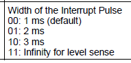
>Bit1-0 WIDTH 1ms, 2ms, 3ms, Infinity for level sense


Q1:
What is the target of "level sense"?
Energysense or Contolsense or Both?


Q2:

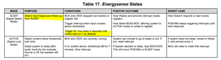
Intterupt events can be selected with Register #96.
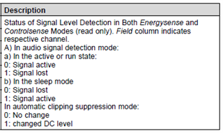
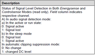
 - Clipping, DC Level Change(Controlsense), DIN, Energysense.

When ether or both events of "DC Level Change" and "Energysense" are triggered, can INT output pulse with infinite width?
Contrary, When "Clipping" or "DIN" events are tirggered, can the width of pulse be set to 1,2,3 or 4ms?

I'd appreciate it if you could give me advice.

  • One more question.

    The detail of the intterupt status can be checked in SIGDET_STAT (Register #50)

    Page.58
    > Step 3: Read the SIGDET_STAT (Page.0 0x32) to see which channel changed.

    Page.115 (Register #50, 0x32)

    Page.115 says: In "automatic clipping suppression mode:", this register shows "chaned DC level".
    This register can show the status for "Signal Detection" and "Automatic Clipping".

    Q3:
    I want to trigger controlsense interruption for the "level change detection" (out of the REF_LEVEL +/-DIFF_LEVEL).
    Can I check this status in Register #50?

  • Hi KISO-san,

    Q1:

    The pulse width is defined for both controlsense and energysense. Figure 35 & 44 of the datasheet is a good reference for the flow of the interrupt controller.

    Q2:

    Somewhat answered by Q1, the pulse duration of the interrupt is set for all interrupt sources. There is not a way to configure the device to have different interrupt pulse widths for varying sources.

    Q3:

    The process for triggering and reading the controlsense interrupt is best explained in 9.5.3  - 9.5.3.5 of d/s. This is also explained in section 9.3.10.3.

    Best Regards,

  • Dear Douglas-san,
    Thank you for your advice.
    Sorry for the mistakes about page numbers and section numbers on the datasheet,
    because there are difference between english and japanese version...


    Q1 & Q2:
    >the pulse duration of the interrupt is set for all interrupt sources.

    In Table 102 (Datasheet Page.124), Reg
    ister #98 Bit[1-0] WIDTH of data 0b11 shows "11: infinity for level sense".
    Your adviced is that : pules width setting is "for all interrupt source", not only "level sense".
    Is the term of "for level sense" in Table 102 scribal error?


    On the other hands, in section "9.3.15 Interrupt Controller" (Page.56),
    the pulse width varies within 1,2,3,4ms, and pulse "cannot remain asserted, no hold fucntion" = not infinity.

    >The pulse width of the interrupt signal can be changed between 1ms, 2ms, 3ms and 
    4ms.
    >The interrupt controlled cannot remain asserted, the status bits can be sticky, but the interrupt pin itself has no hold function.

    Table 102 and section 9.3.15 are contradictory.
    Does the data 0b11 means "infinity for all interrupt source" or  "4ms for all interrupt source"?

    =============================

    Q3:
    > the controlsense interrupt is best explained in 9.5.3  - 9.5.3.5 of d/s. 

    On the section 9.5.3.4, 
    > Check which input caused the interrupt; in this case, looking for (4R) SIGDET_STAT (0x32).

    So, I want to know the detail of SIGDET_STAT.


    Table 69 Register 50 (0x32) SIGDET_STAT on page of data sheet 114.


    Does "Controlsense in Active mode" correspond to "A) In audio signal detection mode a) In the active or run state" on the Table 69?
    This shows the flag of Signal active/lost. It might be for energy sense.

    According to the Table 69, "In automatic clipping suppresion mode", this bit shows the flag of "Change of DC level".
    This flag is for clipping suppresion function, not for control sense.

    I want to trigger controlsense interruption for the "level change detection" (out of the REF_LEVEL +/-DIFF_LEVEL).
    Can I check this status in Register #50? How is the interrupt channel and status shown in the registers?

  • Hi KISO-san,

    Thank you for catching the contradictory statements.

    Q1 & Q2

    >The pulse width of the interrupt signal can be changed between 1ms, 2ms, 3ms and 4ms.
    >The interrupt controlled cannot remain asserted, the status bits can be sticky, but the interrupt pin itself has no hold function.
    Is the term of "for level sense" in Table 102 scribal error?

    I believe this is scribal error in the description hence why section 9.3.15 states "The pulse width of the interrupt signal can be changed between.." in reference to the 4 signals interrupts that are monitored. All of the signals being monitored are some form of level sense but it would be more clear to state interrupt source.

    In addition, "infinity for level sense" is referring to the status of the interrupt status being a sticky flag (status of 1 flag is triggered once until cleared) as opposed to pulsing the status of the interrupt every Xms.

    Q3:

    Does "Controlsense in Active mode" correspond to "A) In audio signal detection mode a) In the active or run state" on the Table 69?

    Your statement is Correct, "Audio signal detection mode" is referring to Active and Sleep modes.

    According to the Table 69, "In automatic clipping suppresion mode", this bit shows the flag of "Change of DC level".
    This flag is for clipping suppresion function, not for control sense.

    Correct, partially. The device will either be in audio signal detection mode (default) or DC level change detection mode. Register 48 (0x32)

    Can I check this status in Register #50? How is the interrupt channel and status shown in the registers?

    Triggering controlsense interruption is explained in 9.3.10.3. Read in 16bit two's complement. Status & Reset instructions in 9.3.15.2.3

  • Douglas-san,
    Thank you for your kindly advices. 

    I understand that:
      - Interrupt pulse width can be 1ms,2ms,3ms,4ms for all interrupt sources.
      - Register 97 INT_STAT (DC_CHANGE) is sticky flag.
      - Register 50 SIGDET_STAT shows the controlsense status.

    May I have a few more questions?

    --------

    >The device will either be in audio signal detection mode (default) or DC level change detection mode. Register 48 (0x32)
    Is SIGDET_CH_MODE (Register 48) effective in active mode?

    In Section 9.5.3.2, SIGDET_CH_MODE is using for control sense as Acitve mode flow.
    > Set 4R as controlsense input (for example, a control voltage for volume control) using SIGDET_CH_MODE (0x30)

    But, Table 67 shows:
    > Select the signal detection mode for each channel in SLEEP mode

    I think SIGDET_CH_MODE is effective for only SLEEP mode.
    Is the descritpion "in SLEEP mode" scribal error?

    --------

    In controlsense DC level change detection mode in Active Mode, is SIGDET_STAT register sticky?

    Section 9.3.15.2.2. shows: SIGDET_STAT is not sicky in Energysense in Sleep Mode.
    > INT_STAT (Page.0 0x61) is sticky and SIGDET_STAT (Page.0 0x32) is not sticky in this mode. 

    But in the section 9.3.15.2.3 (control sense), there are no comments about this.

    --------

    As shown in Figure 36, an interrupt will be generated when the input  level is out of REF range (over or less than REF_LEVEL +/- DIFF_LEVEL).
    As to Table 69 of SIGDET_STAT, the status of DC level change detection is :0=No change, 1=Changed.

    Does the status of "1=Changed" mean out of REF range?

    --------

    You said: "pulsing the status of the interrupt every Xms."
    For controlsense, is short width(1 - 4ms) pulses output repeatedly?

    The pulse width of output INT signal is Xms (according to Register 98 WIDTH).
    If the signal level remains out of REF range, and INT_EN has not been disabled yet, INT signal will output again with the specified interval time?
    Can I set this interval time by Register 54 INT_INTVL for DC level change detection? (INT_INTVL might be the detection interval in sleep mode...)

  • Hi,

    Is SIGDET_CH_MODE (Register 48) effective in active mode?

    It is effective in both active and sleep mode. 

    "This feature (thresholds and interrupts) is available in both active and sleep modes. In sleep mode, the device automatically scans through each channel designated a controlsense input. In active mode, the scanning will need to be done manually by a host microcontroller by modifying the SEC_ADC_INPUT_SEL (Page.0, 0x0A) register." - [9.3.10.3]

    In controlsense DC level change detection mode in Active Mode, is SIGDET_STAT register sticky?

    SIGDET_STAT appears to be sticky for controlsense, this can be seen in 9.5.3.(1-6) diagram because the register needs to be cleared and an update to system settings after troubleshooting.

    Does the status of "1=Changed" mean out of REF range?

    Correct

    For controlsense, is short width(1 - 4ms) pulses output repeatedly?

    Correct, however I want to clarify that I believe the 4ms is scribal error, 1- 3ms is the true range. We recommend following the register map for definitive pulse widths.

    PCM186x will trigger interrupts until host responds. [9.3.11]

    If the signal level remains out of REF range, and INT_EN has not been disabled yet, INT signal will output again with the specified interval time?

    Not completely sure I understand the question, but if by INT you mean INT_STAT, then that is correct.

    Can I set this interval time by Register 54 INT_INTVL for DC level change detection?

    This register is essentially for this condition of energysense/controlsense: 

    Thank you for your patience,

  • Douglas-san,
    Thank you for answering me many times.


    >> ...INT signal will output again with the specified interval time?
    >Not completely sure I understand the question, but if by INT you mean INT_STAT, then that is correct.

    I wrote "INT signal" in the sense of "the signal output from ports (INTA, INTB or INTC)".


    I understand:
     Available settings of the register #98 Bit[1-0] WIDTH are: 00(1ms) - 10(3ms).
     Pulse interval time can be set by INT_INTVL for controlsense as same as energysense.

    All my questions have been cleard.
    Thank you for much.