This thread has been locked.

If you have a related question, please click the "Ask a related question" button in the top right corner. The newly created question will be automatically linked to this question.

TPA3255: Speakers External Load Diagnostics

Part Number: TPA3255
Other Parts Discussed in Thread: TAS6424E

Hello

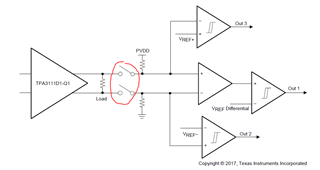
i have a question about the Speakers Diagnostics circuit that is specified in the "Class-D Amplifier External Load Diagnostics" document from 2017:

first i would like to note that i'm using the TPA3255 ic and using the diagnostic circuit while disconnecting the TPA3255 through a relay (only speakers conected).

1) is there a updated / newer or a better circuit ?

2) as reading the document am not sure which parts values to change in order to set the threshold

for an example short circuit under 4 Ω which resistor and what are the values range to chose ?

3) is this circuit can be considered reliable ?

4) is there an IC with "built in" circuit for easier implementation ?

thanks in advance

4403.slva824.pdf

  • Hi Ilya

    1) is there a updated / newer or a better circuit ?

    Sorry, no update about it, and load detect is not a common requirement for consumer side products. 

    2) as reading the document am not sure which parts values to change in order to set the threshold

    for an example short circuit under 4 Ω which resistor and what are the values range to chose ?

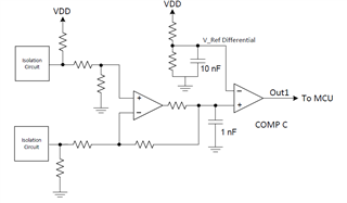
    As below picture, you could consider your 4ohm load is connected between the two "Isolation Circuit". All the resistors in the picture could be adjusted, and you could decide a suitable voltage for the positive input of COMP C, maybe 1/2VDD. And also set the negative of COMP C to 1/2VDD, use two same value resistor would be fine. Then your COMP C would change logic when load smaller than 4ohm.

    3) is this circuit can be considered reliable ?

    As long as your "Isolation Circuit" reliable would be fine. All the detection circuit must be isolated with the load when TPA3111/TPA3255 starts working. Only could detect before the PLAY.

    4) is there an IC with "built in" circuit for easier implementation ?

    Our automotive device has built in load diag function. Like TAS6424E, TAS6584. Consider the output power level, TAS6584 maybe more suitable to you.

  • Hi Shadow He

    thank you for your replay,

    please tell me, on page 8 in the document (the schematic) there are 3 resistors of 2k (R17, R18, R19) that used as a pull up resistors, why they are 2K ?

    is there any special reason ?

    can a 10K resistor be used instead of 2K ?

  • Hi Shadow He

    thank you for your replay,

    please tell me, on page 8 in the document (the schematic) there are 3 resistors of 2k (R17, R18, R19) that used as a pull up resistors, why they are 2K ?

    is there any special reason ?

    can a 10K resistor be used instead of 2K ?

  • Hi Ilya

    please tell me, on page 8 in the document (the schematic) there are 3 resistors of 2k (R17, R18, R19) that used as a pull up resistors, why they are 2K ?

    These are comparator output pull up. This comparator is open drain output, it need this resistor to output high level voltage. Use 10K also should be fine, only the rising time may a little longer.