This thread has been locked.

If you have a related question, please click the "Ask a related question" button in the top right corner. The newly created question will be automatically linked to this question.

TLV320AIC3204: Input to output crosstalk

Part Number: TLV320AIC3204


Hi,

The AIC3204 specifies input channel separation with the following test conditions.

1kHz sine wave input at -3dBFS
Single-ended configuration
IN1_L routed to Left ADC
IN1_R routed to Right ADC, Rin = 20kΩ
AGC = OFF, AOSR = 128,
Channel Gain = 0dB, CM = 0.9V

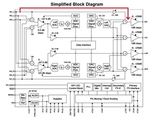
Because the AIC3204 can route the analog input to the analog output directly, we are interested in the separation between input and output.

The datasheet does not mention anything about the isolation between IN1_x and the output.

If the IN1_x to output isolation is unknown, we are also interested if the isolation between, for instance, IN2_L and IN2_R are the same as the specification for IN1_L and IN1_R (108dB), as the input to input channel separation is only specified for IN1_L and IN1_R.

  • Hi Marjin,

    The isolation between IN1_X and the output isn't spec'd the same way because it doesn't have any meaning. Correct me if I misunderstand but you can't have cross talk between an input and output in the same path. If it is connected, then your gain is as specified by the connection path. If it is not connected, then it is completely removed from the path (theoretically -inf dB cross talk).

    As for IN2_L and IN2_R, since the test condition isn't tested I can't give you an official number, but the IN1_L and IN1_R separation can be used as a close estimate to the IN2_x channel separation.

    Best regards,
    Jeff McPherson 

  • Hi Jeff,

    Thank you for your answer. I don't think I have made myself clear. I'll try to explain myself using an example.

    I think there are two paths:

    1. The analog path between input and output (red)

    2. The AD input → data interface to the processor → DA output (green)

    If path 2 is used, and path 1 is not used, the processor connected to the data interface will introduce a delay, which it most certainly will, the red path will introduce distortion as a result of non ideal isolation between input and output.

    If I'm not mistaken, the analog input path can be attenuated from 0 to -72dB, and then can be routed directly to the output. It can't be the case that there is -inf dB crosstalk between input and output, right?

    I hope I have explained my concerns clearly. If not, please don't hesitate to say so.

    Regards,

    Marijn

  • Hi Marjin,

    Thank you for the clarification. I think the diagram misled you. The red path can be disconnected completely from interfering with the green path in page 1, register 12, D2. Imagine a switch in-between the attenuator and the summation point. That attenuator you're seeing is controlled in page 1 register 22. So yes the attenuator is limited to -72dB but the path can be fully disconnected from the summation point with a different register setting if no signal mixing is desired. 

    Hope this clears things up,
    Jeff McPherson