This thread has been locked.

If you have a related question, please click the "Ask a related question" button in the top right corner. The newly created question will be automatically linked to this question.

TLV320ADC3140: TLV320ADC3140 with Ti AM625 SoC, 4Ch analog can't record

Part Number: TLV320ADC3140

Hi Teams,

Our product is using TLV320ADC3140 codec. we want to record 4Ch analog mic with TDM mode.

However, we always record failed with below message:

arecord: pcm_read:2221: read error: Input/output error

ALSA record command:

# arecord -f dat -t wav -c 4 4ch.wav

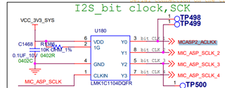
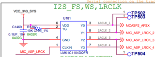
This codec MCLK, BCLK, FCLK is input from a clock generator.

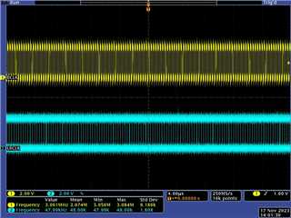
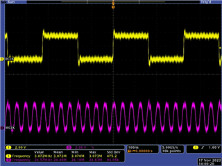
The oscilloscope measurement signals are 24.576MHz, 3.072MHz, and 48KHz respectively.

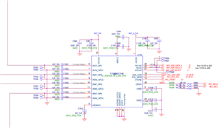
CPU side is using MCASP2. AXR5 is rx connect with tlv320adc3140's SDOUT.

ACLKX, AFSX is input from clock generator,too.

ACLKX = 3.072MHz.

AFSX = 48KHz

Below is my device tree:

&main_pmx0 {
    mcasp2_pins_default: mcasp2-pins-default {
        pinctrl-single,pins = <
            AM62X_IOPAD(0x0178, PIN_INPUT, 2) /* (AC20) RGMII2_TD3.MCASP2_ACLKX */
            AM62X_IOPAD(0x0174, PIN_INPUT, 2) /* (AD21) RGMII2_TD2.MCASP2_AFSX */
            AM62X_IOPAD(0x0184, PIN_INPUT, 2) /* (AE23) RGMII2_RD0.MCASP2_AXR2 */
            AM62X_IOPAD(0x0164, PIN_OUTPUT, 2) /* (AA19) RGMII2_TX_CTL.MCASP2_AXR4 */
            AM62X_IOPAD(0x0168, PIN_INPUT, 2) /* (AE21) RGMII2_TXC.MCASP2_AXR5 */
        >;
    };
};

/* Redefine rgmii2 pins avoid pinctrl conflict */
&main_rgmii2_pins_default {
    pinctrl-single,pins = <
        AM62X_IOPAD(0x188, PIN_INPUT, 0) /* (AB20) RGMII2_RD1 */
        AM62X_IOPAD(0x18c, PIN_INPUT, 0) /* (AC21) RGMII2_RD2 */
        AM62X_IOPAD(0x190, PIN_INPUT, 0) /* (AE22) RGMII2_RD3 */
        AM62X_IOPAD(0x180, PIN_INPUT, 0) /* (AD23) RGMII2_RXC */
        AM62X_IOPAD(0x17c, PIN_INPUT, 0) /* (AD22) RGMII2_RX_CTL */
        AM62X_IOPAD(0x16c, PIN_OUTPUT, 0) /* (Y18) RGMII2_TD0 */
        AM62X_IOPAD(0x170, PIN_OUTPUT, 0) /* (AA18) RGMII2_TD1 */
    >;
};

&main_i2c2 {
    status = "okay";
    pinctrl-names = "default";
    pinctrl-0 = <&i2c2_pins_default>;
    clock-frequency = <400000>;

    tlv320adc3140: audio-codec@4c {
        status = "okay";
        #sound-dai-cells = <0>;
        compatible = "ti,tlv320adc3140";
        reg = <0x4c>;
        pinctrl-names = "default";
        pinctrl-0 = <&audio_mic_rst_pins_default>;

        ti,mic-bias-source = <0>;
        ti,pdm-edge-select = <1 1 1 1>;
        ti,gpio-config = <10 0>;
        ti,gpi-config = <0 0 0 0>;

        ti,gpo-config-1 = <0 0>;
        ti,gpo-config-2 = <0 0>;
        ti,gpo-config-3 = <0 0>;
        ti,gpo-config-4 = <0 0>;
        ti,slot-mapping = <0 1 2 3>;
        ti,asi-tx-driver = <0>;

        reset-gpios = <&main_gpio1 6 GPIO_ACTIVE_HIGH>;
    };
};

&tlv320_mclk {
    clock-frequency = <24576000>;
};

&mcasp1 {
    status = "disabled";
};

&mcasp2 {
    status = "okay";
    #sound-dai-cells = <0>;

    pinctrl-names = "defualt";
    pinctrl-0 = <&mcasp2_pins_default>;

    op-mode = <0>;
    tdm-slots = <4>;
    //assigned-clock-rates = <24576000>;

    num-serializer = <6>;
    serial-dir = <
            0 0 1 0 1 2
    >;

    tx-num-evt = <32>;
    rx-num-evt = <32>;
};

&codec_audio {
    /delete-property/ simple-audio-card,widgets;
    /delete-property/ simple-audio-card,routing;
    simple-audio-card,format = "i2s";
    simple-audio-card,widgets = "Microphone", "Mic";
    simple-audio-card,routing =
        "MIC1P", "Mic",
        "MIC1M", "Mic",
        "MIC2P", "Mic",
        "MIC2M", "Mic",
        "MIC3P", "Mic",
        "MIC3M", "Mic",
        "MIC4P", "Mic",
        "MIC4M", "Mic";
    //mclk-fs = <512>;

    simple-audio-card,bitclock-master = <&sound_cpu>;
    simple-audio-card,frame-master = <&sound_cpu>;

    sound_cpu: simple-audio-card,cpu {
        sound-dai = <&mcasp2>;
        clocks = <&tlv320_mclk>;
        dai-tdm-slot-num = <4>;
        dai-tdm-slot-width = <32>;
        dai-tdm-slot-rx-mask = <1 1 1 1>;
    };

    simple-audio-card,codec {
        sound-dai = <&tlv320adc3140>;
        dai-tdm-slot-num = <4>;
        dai-tdm-slot-width = <32>;
        dai-tdm-slot-tx-mask = <1 1 1 1>;
    };
};

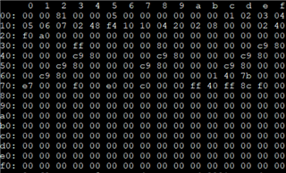
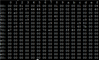
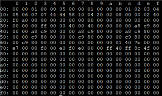
Below is i2c register when record.
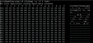
Is there any content that is wrong?

  • Kindly offer following information

    kernel version, and where have you download the driver code, and measure the bitclk and ws clk with scope, and upload the waveform.

    I skim the key register setting for audio signal. some register setting seem not fine.

    R0x7: 0x44, seem for I2S, 16bit, it should be 0x04

    The root cause seemed arecord -f dat, dat means 48kHz, 16bit, stereo, far from your 4-slot tdm requirement.

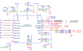
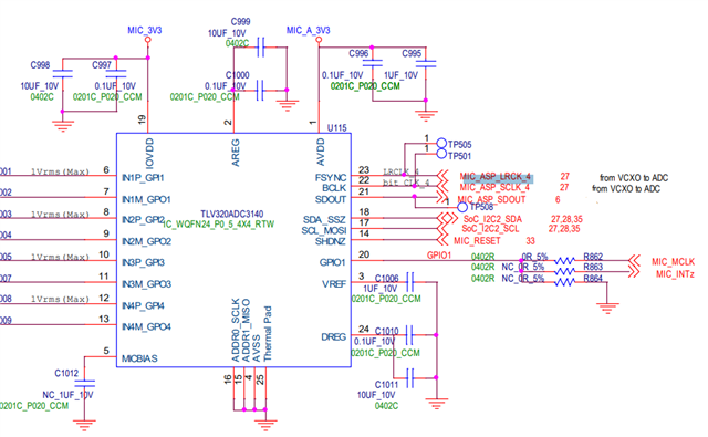
    One more thing, can you also share the schematic? Some register setting highly depend on hardware connection.

  • Linux kernel version is 6.1.33 from AM62 09_00_00_03 SDK

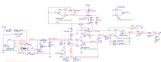
    Here's schematic.

    Update Register dump , Devicetree setting about simple-audio-card,format "i2s" -> "dsp_b" (for tdm mode)

    R0x7 register is change to 0x00 

    I have a question:

    1. According to our hardware layout design, who should be master at simple-audio-card,bitclock-master and simple-audio-card,frame-master ?

    mcasp2? tlv320adc3140? or doesn't need both property setting?

    It will take some time for the clock waveform to be provided. Here provide the clk settings first.

    Here's wave

  • According to your setting in devicetree

    simple-audio-card,bitclock-master = <&sound_cpu>;
    simple-audio-card,frame-master = <&sound_cpu>;

    the master is platform. Why not set dsp-a?

    Then why R0x7 not to be set as 0x04? According to your wave form? the clk seemed i2s, 32-bit, 3.072MHz, and 48kHz.

  • I'm not sure devicetree setting about simple-audio-card,frame-master and simple-audio-card,bitclock-master.

    should set CPU or Codec? or both don't need to set ?

    Should I setting to dsp-a ?
    R0x7 is 
    according to simple-audio-card,format. Set to dsp-a, R0x7 will be 0x00.

    Our clock setting is for 16-bit 48K channel. So BCLK = channel num * 48K * 16-bit = 3.072MHz.

    But I don't know why can't record.

  • As to the platform setting, kindly consult the platform vendor.

    As I pointed before, you use the wrong parameter to arecord command. And I'm sure that the driver code you get only support basic feature, you will add some code to meet your requirement.For 4-slot. 16bit, the r0x7 should be 0x04.

    This is the datasheet lnk TLV320ADC3140 data sheet, product information and support | TI.com

    Hope this can help you.

  • Thanks for you reply.

    I thinks problem is on the device tree setting and mcasp.

    4 analog mic in -> tlv320adc3140 -> SDOUT -> Ti-AM625 mcasp2 AXR5

    I try to enter command : arecord -f dat -t wav -c 8 file.wav

    It would not print any error message.

    But there is no data and file size is always 44kb.

    We want 4 channel, command should be "arecord -f dat -t wav -c 4 file.wav". And I am wrong? 

  •  please use this command setting "arecord -r 48000 -t wav  -f S16_LE -c 4  file.wav"

    -f dat is for stereo

    The reason why the data is zero is that the audio data have not been into the system buffer.

  • Ok ! 

    I check my pinctrl-map, found my mcasp2 pinctrl name is wrong

    device 2b20000.audio-controller
    state default
    type MUX_GROUP (2)
    controlling device f4000.pinctrl
    group mcasp2-pins-default
    function mcasp2-pins-default

    and using  "arecord -r 48000 -t wav  -f S16_LE -c 4  file.wav" already record file.

    But file is no data.

  • dump the regsiter again

  • Here's register

    I have been change codec as master on device tree.

  • Also share the devicetree 

  • &main_pmx0 {
        mcasp2_pins_default: mcasp2-pins-default {
            pinctrl-single,pins = <
                AM62X_IOPAD(0x0178, PIN_INPUT, 2) /* (AC20) RGMII2_TD3.MCASP2_ACLKX */
                AM62X_IOPAD(0x0174, PIN_INPUT, 2) /* (AD21) RGMII2_TD2.MCASP2_AFSX */
                AM62X_IOPAD(0x0184, PIN_INPUT, 2) /* (AE23) RGMII2_RD0.MCASP2_AXR2 */
                AM62X_IOPAD(0x0164, PIN_OUTPUT, 2) /* (AA19) RGMII2_TX_CTL.MCASP2_AXR4 */
                AM62X_IOPAD(0x0168, PIN_INPUT, 2) /* (AE21) RGMII2_TXC.MCASP2_AXR5 */
            >;
        };
    };
        
    
    &mcasp2 {
        status = "okay";
        #sound-dai-cells = <0>;
    
        pinctrl-names = "default";
        pinctrl-0 = <&mcasp2_pins_default>;
    
        op-mode = <0>;
        tdm-slots = <4>;
        //assigned-clock-rates = <24576000>;
    
        //num-serializer = <6>;
        serial-dir = <
            0 0 1 0
            1 2 0 0
            0 0 0 0
            0 0 0 0
        >;
    
        tx-num-evt = <32>;
        rx-num-evt = <32>;
    };
    
    &codec_audio {
        /delete-property/ simple-audio-card,widgets;
        /delete-property/ simple-audio-card,routing;
        simple-audio-card,format = "dsp_a";
        simple-audio-card,widgets = "Microphone", "Mic";
        simple-audio-card,routing =
            "MIC1P", "Mic",
            //"MIC1M", "Mic",
            "MIC2P", "Mic",
            //"MIC2M", "Mic",
            "MIC3P", "Mic",
            //"MIC3M", "Mic",
            "MIC4P", "Mic";
            //"MIC4M", "Mic";
        mclk-fs = <512>;
    
        ///delete-property/simple-audio-card,bitclock-inversion;
        ///delete-property/simple-audio-card,bitclock-master;
        ///delete-property/simple-audio-card,frame-master;
        simple-audio-card,bitclock-master = <&sound_master>;
        simple-audio-card,frame-master = <&sound_master>;
    
        sound_cpu: simple-audio-card,cpu {
            sound-dai = <&mcasp2>;
            clocks = <&tlv320_mclk>;
            dai-tdm-slot-num = <4>;
            dai-tdm-slot-width = <16>;
            dai-tdm-slot-rx-mask = <1 1 1 1>;
        };
    
        sound_master: simple-audio-card,codec {
            sound-dai = <&tlv320adc3140>;
            clocks = <&tlv320_mclk>;
            dai-tdm-slot-num = <4>;
            dai-tdm-slot-width = <16>;
            dai-tdm-slot-tx-mask = <1 1 1 1>;
        };
    };


  • Can you please send me the schematic with the ADC . I dont see it 

  • Here's ADC side

  • Are you coupling the signals differentially?

    Are the Signals AC  or DC Coupled?

  • Mic is single-ended

    IN1M to GND

    I thinks problem is about mcasp2 and tlv320adc3140 both are slave

    According to product requirement, Clock generator Si5351B output MCLK/BCLK/FCLK since boot.

    So I don't know how to configure devicetree.

    Mic 1 side


    connect to ADC

  • This is a single ended AC Coupled application.

    As a first step please check if the Mic signal is reaching the ADC Pin. To do this make a 1Khz tone from You tube in your mobile phone and put close to the Mic. Then measure with an oscilloscope the DC Voltage on the input pin of thje ADC. You should see a 1Khz signal Riding on a DC Level.

    As a second step where is the Source of the BCLK and LRCK Signals?

  • 1. Mic already connect to ADC,

    We heve testing on AM62 SK EVM with TLV320ADC3140.

    2. BCLK, LRCLK from externel clock generator IC.

    Today, our team got some patches from Customer and Ti.

    This patches is work for Custom prototype.

    Patches let McASP can receive extclk, and devicetree need to set McASP as Master.

    This setting let McASP force below setting

    case SND_SOC_DAIFMT_BC_FC:
    /* codec is clock and frame master */
    mcasp_clr_bits(mcasp, DAVINCI_MCASP_ACLKXCTL_REG, ACLKXE);
    mcasp_clr_bits(mcasp, DAVINCI_MCASP_TXFMCTL_REG, AFSXE);

    mcasp_clr_bits(mcasp, DAVINCI_MCASP_ACLKRCTL_REG, ACLKRE);
    mcasp_clr_bits(mcasp, DAVINCI_MCASP_RXFMCTL_REG, AFSRE);

    /* BCLK */
    clear_bit(PIN_BIT_ACLKX, &mcasp->pdir);
    clear_bit(PIN_BIT_ACLKR, &mcasp->pdir);
    /* Frame Sync */
    clear_bit(PIN_BIT_AFSX, &mcasp->pdir);
    clear_bit(PIN_BIT_AFSR, &mcasp->pdir);

    mcasp->bclk_master = 0;
    break;

    So, here's only one things.

    We need to configure TLV320ADC3140 as slave and DOUT should output TDM data.

    Below is i2c register table now.

  • TEST_4ch_single_ended.cfg

    I am including a file having I2C settings for 4 Channel Single ended ADC. Please check

  • We have been record successful.

    Root cause : Some rework cause board damage and change McASP register 

    Thanks for everyone help !