This thread has been locked.

If you have a related question, please click the "Ask a related question" button in the top right corner. The newly created question will be automatically linked to this question.

TAS5760M: I2C NACK Issue in Software Control

Part Number: TAS5760M

Dear teams,

There is an issue that our LSI cannot get ACK from the device when accessing registers via the I2C control port.

This phenomenon is occurring on our multiple test boards.

When accessing the I2C control port, we have confirmed that the startup sequence in the data sheet is met.

We have attached the waveforms we measured. Could you please take a look at it? The slave address is 0x6C, which is correct.

We have also confirmed that the AC characteristics of the I2C Control Port in the datasheet is met. Therefore, we don't think there is a problem with the waveforms.

Similarly, no ACK is returned for slave address 0x6D.
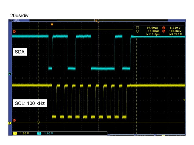
Have you reported any similar issue?

Could you please give me your advice regarding this problem?

Sincerely,

Takuma Ito

  • Hi Takuma,

    Our colleague is on sick leave. 

    He will rely you when he is coming company.

    Best Regards,

    Donny Peng

  • Hi Donny,

    Please tell him to take care of himself.

    However, When would I expect to hear back from him?

    Best Regards,

    Takuma Ito

  • Hi Takuma

      Your waveform indeed seems this way. But I2C is rarely met any problem.

      How about the power supply at AVDD and DVDD? The clock we sent into MCLK/SCLK/LRCK, are they stable and what is the frequency? And about the SPK_SD and SPK_FAULT pins, what is the status?

  • Hi Shadow

    The voltage of AVDD is 12V or 24V. DVDD is 3.3V.

    MCLK/SCLK/LRCK are stable. The frequencies are 22.579 MHz, 2.822 MHz, and 44.1 kHz, respectively. We think this meets the datasheet.

    The status of SPK_SD is Low, but it cannot get an ACK even if it is High.
    SPK_FAULT status is always High. This pin is not asserted low.

    Is there anything else I should check?

  • Hi Takuma

      Seems more strange now. 

      May I ask how many samples did we test for now? Are we able to put 1PCS on the EVM to double check?  

  • Hi Shadow

    There are two development boards and three or more prototype machines. Every board we own fails to communicate.

    Are we able to put 1PCS on the EVM to double check? 

    We are planning to try the method you suggested.

    By the way, our LSI has successful I2C communication with devices other than TAS5760M. If you have any experience like this, could you please tell me how you solved it? Is there anything I should check?

  • Hi Takuma

       For this device, we could still check the two SPK_GAIN pins need to be pulled HIGH, in order to make device into Software Control Mode. 

       The other perspective would be hard to think of, the I2C function is quite stable actually.

  • Hi Ito-san,

    Sorry for cutting in.
    Unfortunately, I couldn't find the root cause for this issue.
    PBTL/SCL and FREQ/SDA are probably connected to DVDD via pull-up resistors. If the power-up of power supply voltage VCC for I2C master device is slower than DVDD, please try connecting PBTL/SCL and FREQ/SDA to VCC via pull-up resistors.

    Best regards,
    Kato

  • Hi Kato-san,

    Thank you for contacting us.
    Since VCC and DVDD are the same power supply, the power-up timing is the same.

  • Hi Shadow,

    Thank you very much for all your advice.
    We re-checked the I2C data hold time and found that it did not meet the specifications in the TAS5760M datasheet.
    After correcting the data hold time, I was able to get an ACK from the TAS5760M.

    I have one additional question. The TAS5760M data sheet does not mention the maximum hold time.
    On the other hand, according to the "UM10204 I2C-bus specification and user manual", the maximum hold time in Fast-mode is 0.9us.

    Could you please tell me why there is a difference between the TAS5760M data sheet and "UM10204 I2C-bus specification and user manual"?
    If there is a difference, does the TAS5760 datasheet take precedence?

  • Hi Takuma

    We re-checked the I2C data hold time and found that it did not meet the specifications in the TAS5760M datasheet.
    After correcting the data hold time, I was able to get an ACK from the TAS5760M.

    It's glade we find out the problem. I'm just curious that do you mean the Hold time at START condition, 0.6us? From the waveform, the time seems enough, maybe the SDA shouldn't goes up before SCL pulled low, it's a good catch.

    I have one additional question. The TAS5760M data sheet does not mention the maximum hold time.
    On the other hand, according to the "UM10204 I2C-bus specification and user manual", the maximum hold time in Fast-mode is 0.9us.

    Do you mean the tvd;dat, and tvd;ack? Seems only this two value has max 0.9us requirement.

    They both have comment 4, says "This maximum must only be met if the device does not stretch the LOW period (tLOW) of the SCL signal. If the clock stretches the SCL, the data must be valid by the set-up time before it releases the clock."

    It is trying to say that data setup time is actually the most important value, we need to firstly guarantee.  During low period of SCL, there would be rinsing/falling time if data need to change, and tsu;dat/tvd;dat/tvd;ack we asked, also the data set up time need to guarantee. The minimum low period SCL is 1.3us, the maximum rising/falling time is 0.3us, and we must guarantee 0.1us data setup time. So, if you calculate it, only 0.9us left as maximum. It's just the corner situation need this requirement. So if you stretch the low period of SCL, the situation we usually do, the 0.9us requirement is gone. TAS5760 datasheet simply removed this requirement, our more older devices still has it, and lots of customer have mentioned this requirement not make sense.

    Could you please tell me why there is a difference between the TAS5760M data sheet and "UM10204 I2C-bus specification and user manual"?
    If there is a difference, does the TAS5760 datasheet take precedence?

    There's shouldn't be much differences, the TAS6760 requirement should all coming from this Standard.

  • It's glade we find out the problem. I'm just curious that do you mean the Hold time at START condition, 0.6us? From the waveform, the time seems enough, maybe the SDA shouldn't goes up before SCL pulled low, it's a good catch.

    I said that data hold time means tHD;DAT. I2C communication failed because "tHD;DAT" was negative.

    Do you mean the tvd;dat, and tvd;ack? Seems only this two value has max 0.9us requirement.

    I was referring to the maximum value of "tHD;DAT". The I2C standard says "The maximum tHD;DAT could be 3.45 μs and 0.9 μs for Standard-mode and Fast-mode".

    Thank you for your explanation. I was able to understand why the maximum value of "tHD;DAT" was removed in TAS5760M. I also understand that there is not much difference.