This thread has been locked.

If you have a related question, please click the "Ask a related question" button in the top right corner. The newly created question will be automatically linked to this question.

TLV320ADC6120: TLV320ADC6120 clock issue using internal LDO

Part Number: TLV320ADC6120
Other Parts Discussed in Thread: TLV320ADC3120, TLV320DAC3203

Hi, I am having a clock issue with TLV320ADC6120

I am using internal LDO.

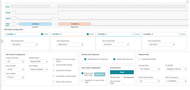
here is my setup code. I am trying to configure the ADC as MASTER with 12.288mhz mclk as clock but using PLL to generate WCLK and BCLK.

I2S 48khz 24bit 2 channel. WCLK should be 48khz.

I seam to get this incorrect WCLK and BCLK whatever setting I use.

I2C is ACK all the register writes on the bus. the MCLK is a stable 12.288mhz 
here is my setup code.

/* ######################## ADC TLV320ADC6120 SETUP ############################## */


// register pages

// Page 0x00 normal setup registers ,
// Page 0x01 VAD voice activity detection
// Page 0x02 Programmable Coefficient Registers:
// Page 0x03 Programmable Coefficient Registers:7 -12
// Page 0x04 Mixer Settings

/* go to page 0 */
ADC_I2C_Write(PAGE_CFG, 0x00);


// SW_RESET Register(Address = 0x1)[Reset = 0x0]
ADC_I2C_Write(SW_RESET, 0x01);

osDelay(10u); /* 10ms. */

/* go to page 0 */
ADC_I2C_Write(PAGE_CFG, 0x00);


// Wake-up device by I2C write into P0_R2 using internal AREG

// bit 7 = 1 | 1d = Internally generated 1.8 - V AREG supply using an on - chip regulator(use this setting when AVDD is 3.3 V)
// bits 6-5 = 00 | Reserved bits; Write only reset values 0
// bits 4-3 = 00 | 0d = VREF quick-charge duration of 3.5 ms (typical)
// bit 2 = 0 | 0d = I2C broadcast mode disabled
// bit 1 = 0 | Reserved bit; Write 0
// bit 0 = 1 | 1d = Device is NOT in sleep mode

// BIN 10000001 HEX 0x81

ADC_I2C_Write(SLEEP_CFG, 0x81);

// osDelay(10u); /* 10ms. */

/* go to page 0 */
ADC_I2C_Write(PAGE_CFG, 0x00);


// ******** IN_CH_EN Register input channels config *******************

// bit 7 = 1 | 1d = Channel 1 is enabled
// bit 6 = 1 | 1d = Channel 2 is enabled
// bit 5 = 0 | 0d = Channel 3 is disabled
// bit 4 = 0 | 0d = Channel 4 is disabled
// bits 3-0 = 0000 | reserved write 0000d

// BIN = 11110000 HEX = 0xC0

ADC_I2C_Write(IN_CH_EN, 0xF0);


// ******** BIAS_CFG Register ****************************************

// 7 bit = 0 | reserved write 0
// 6-4 bits = 000 | 0d = Microphone bias is set to VREF (2.750 V, 2.500 V, or 1.375 V)
// 3-2 bit = 00 | reserved write 00
// 1-0 bits = 00 | 0d = VREF is set to 2.75 V to support 2 VRMS for the differential input or 1 VRMS for the single - ended input

// BIN = 00000000 HEX = 0x00

ADC_I2C_Write(BIAS_CFG, 0x00); // try disabling as it worked before !

// *********** GPIO_CFG0 Register ***************

// bit 7-4 = 1010 | 10d = GPIO1 is configured as a master clock input (MCLK)
// bit 3 = 0 | Reserved bit; write 0d
// bit 2-0 = 010 | default , 2d = Drive active low and weak high

// BIN 10100010 HEX = 0xA2

ADC_I2C_Write(GPIO_CFG0, 0xA2);


// CLK_SRC Register(Address = 0x16)

// bit 7 = 1 | 1d = MCLK (GPIO or GPIx) is used as the audio root clock source (the MCLK to FSYNC ratio is as per MCLK_RATIO_SEL setting)
// bit 6 = 0 | 0d = MCLK frequency is based on the MCLK_FREQ_SEL (P0_R19) configuration
// bit 5-3 = 001 | 1d = Ratio of 256
// bit 2 = 0 | reserved write 0
// bit 1 = 0 | 0d = Do not invert BCLK polarity for FSYNC generation
// bit 0 = 0 | reserved write 0.

// BIT 10001000 HEX = 0x88

ADC_I2C_Write(CLK_SRC, 0x88);

// ********* MST_CFG0 Register *************************

// bit 7 = 1 | 1d = Device is in master mode (both BCLK and FSYNC are generated from the device)
// bit 6 = 0 | 0d = Auto clock configuration is enabled (all internal clock divider and PLL configurations are auto derived)
// bit 5 = 0 | 0d = PLL is enabled in auto clock configuration
// bit 4 = 1 | 0d = DO NOT Force gate BCLK and FSYNC when being transmitted from the device in master mode
// bit 3 = 0 | 0d = fS is a multiple (or submultiple) of 48 kHz
// bit 2-0 =001 | 1d = 12.288 MHz MCLK_FREQ_SEL

// BIN = 10000001 HEX = 0x81 // auto clock config
// BUN = 10100001 HEX = 0xE1 // diasable pll?


ADC_I2C_Write(MST_CFG0, 0x81);

// ********* MST_CFG1 Register *************************


// bits 7-4 = 0100 | 4d = 44.1 kHz or 48 kHz FS_RATE Page 0
// bits 3-0 = 0100 | 4d = Ratio of 64 N BCLK clocks in FSYNC cycle

// BIN = 01000100 HEX = 44 64 bclk
// BIN = 01000010 hex = 42 32 bclk

ADC_I2C_Write(MST_CFG1, 0x44);


// ******* ASI_CFG0 Register I2S Mode with 32 Bits/Channel SAI word

// bits 7-6 = 01 | 1d = I2S mode
// bits 5-4 = 10 | 3d = Output channel data word-length set to 32 bits | 2d = Output channel data word-length set to 24 bits
// bit 3 = 0 | 0d = FSYNK Default polarity as per standard protocol
// bit 2 = 0 | 0d = BCLK Default polarity as per standard protocol
// bit 1 = 0 | 0d = Default edge as per the protocol configuration setting in bit 2 (BCLK_POL)
// bit 0 = 0 | 0d = Always transmit 0 for unused cycles , use one for hi-Z

// BIN = 01110001 HEX = 0x70 // 32bit word
// BIN = 01100000 HEX = 0x60 // 24bit word

ADC_I2C_Write(ASI_CFG0, 0x60);

// ASI_CFG1 Register
// bit 7 = 0 | default 0d = Transmit the LSB for a full cycle
//bits 6-5 =00 | default 0d = Bus keeper is always disabled
//bits 4-0 = 00000 | 0d = ASI data MSB location has no offset and is as per standard protocol

ADC_I2C_Write(ASI_CFG1, 0x00);

// ************* ASI_OUT_CH_EN Register **************

// bit 7 = 1 | 1d = Channel 1 output slot is enabled
// bit 6 = 1 | 1d = Channel 2 output slot is enabled
// bit 5 = 0 | 0d = Channel 3 output slot is disabled
// bit 4 = 0 | 0d = Channel 3 output slot is disabled
// bits 3-0 = 0000 | reserved write 0000


// BIN = 11000000 HEX = C0

ADC_I2C_Write(ASI_OUT_CH_EN, 0xC0);


// ********* ASI_CH1 Register Field Descriptions

// bit 7-6 = 00 | Reserved write 00
// bit 5-0 = 000000 | 0d = TDM is slot 0 or I2S, LJ is left slot 0

// BIN = 00000000 HEX = 0x00

ADC_I2C_Write(ASI_CH1, 0x00);


// ********* ASI_CH2 Register Field Descriptions

// bit 7-6 = 00 | Reserved write 00
// bit 5-0 = 000001 | 1d = 1d = TDM is slot 1 or I2S,

// BIN = 00000001 HEX = 0x01

ADC_I2C_Write(ASI_CH2, 0x01);

// **** CH1_CFG0 Register Field Descriptions

// bit 7 = 0 | 0d = Microphone input , 1d = Line input
// bits 6-5 = 01 | 1d = Analog single-ended input | 0d = Analog differential input
// bit 4 = 1 | 0d = AC-coupled input | 1d = DC-coupled input
// bits 3-2 = 01 | 0d = Typical 2.5-kΩ input impedance | 1d = Typical 10 - kΩ input impedance | 2d = Typical 20 - kΩ input impedance
// bit 1 = 0 | reserved write 0
// bit 0 = 0 | 0d = DRE / AGC / DRC disabled | 1d = DRE or AGC or DRC enabled based on the configuration of bit 3 in register 108 (P0_R108)

// BIN = 00101000 HEX = 0x28

ADC_I2C_Write(CH1_CFG0, 0x28);

// **** CH2_CFG0 Register Field Descriptions

// bit 7 = 0 | 0d = Microphone input
// bits 6-5 = 01 | 1d = Analog single-ended input | 0d = Analog differential input
// bit 4 = 1 | 0d = AC-coupled input | 1d = DC-coupled input
// bits 3-2 = 01 | 0d = Typical 2.5-kΩ input impedance | 1d = Typical 10 - kΩ input impedance | 2d = Typical 20 - kΩ input impedance
// bit 1 = 0 | reserved write 0
// bit 0 = 0 | 0d = DRE / AGC / DRC disabled | 1d = DRE or AGC or DRC enabled based on the configuration of bit 3 in register 108 (P0_R108)

// BIN = 00101000 HEX = 0x28

ADC_I2C_Write(CH2_CFG0, 0x28);


// CH1_CFG1 register

// bit 7 - 1 = 1010100 | 84d = Channel gain is set to 42 dB
// bit 0 = 0 | Channel-1 gain sign configuration.
// 0d = Positive channel gain
// 1d = Negative channel gain(minimum channel gain supported till - 11dB; supported only for channel input impedance of 10 - kΩ and 20 - kΩ)

// BIN 10101000 HEX = 0xA8

ADC_I2C_Write(CH1_CFG1, 0x00);

// CH2_CFG1 register

// bit 7 - 1 = 1010100 | 84d = Channel gain is set to 42 dB
// bit 0 = 0 | Channel-1 gain sign configuration.
// 0d = Positive channel gain
// 1d = Negative channel gain(minimum channel gain supported till - 11dB; supported only for channel input impedance of 10 - kΩ and 20 - kΩ)

// BIN 10101000 HEX = 0xA8

ADC_I2C_Write(CH2_CFG1, 0x00);

// ************ PWR_CFG Power - up the ADC, MICBIAS PLL etc Register Field Descriptions *****************

// bit 7 = 1 | 1d = Power up MICBIAS
// bit 6 = 1 | 1d = Power up all enabled ADC and PDM channels
// bit 5 = 1 | 1d = Power up the PLL | 0d = Power OFF the PLL
// bit 4 = 0 | 0d = Channel power-up, power-down is not supported if any channel recording is on
// bits 3-2 = 00 | 0d = Channel 1 and channel 2 are used with dynamic channel power - up, power - down feature enabled
// bit 1 = 0 | 0d = VAD is disabled , Enable voice activity detection (VAD) algorithm
// bit 0 = 0 | reserved use 0
//
// BIN = 11100000 HEX = E0

ADC_I2C_Write(PWR_CFG, 0xE0); // 0xE0 power ON everything including PLL


/* wait for adc to power up */
osDelay(250u);


} //end initADC

Am I missing a crucial register write ? or there is something wrong with hardware design for internal LDO ?

  • Please refer to the below document for configuring the TLV320ADC3120 as an Audio Master.

    https://www.ti.com/lit/an/sbaa495a/sbaa495a.pdf?ts=1701113076338

    Please choose PLL Enabled mode

    The BCLK/FS Ratio in your case is 48. Therefore the BCLK Should be 48kHZ*48=2.304Mhz. This is a supported Frequency

    Below is a snapshot of the registers that need to be enabled

    Schematic: I would suggest removing the external Clamp diode on tjhe input pin.Please keep VDD at 3.3v The schematic is otherwise ok

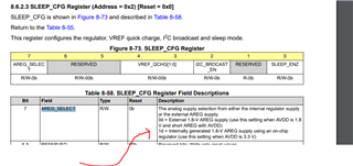
    Also, to select internal regulator, the AREG_SELECT needs to be 1 when using internal regulator

  • Hi Sanjay , thanks for your reply and advise.
    I am supplying 3V3 and there is 1.8V at AREG pin ( the LDO appears to be active )
    I removed the diode protection from inputs in case they are causing issues.
    I already enable AREG_SELECT like this after reset
     
        // Wake-up device by I2C write into P0_R2 using internal AREG

    // bit 7 =    1   |  1d = Internally generated 1.8 - V AREG supply using an on - chip regulator(use this setting when AVDD is 3.3 V)
    // bits 6-5 = 00  |  Reserved bits; Write only reset values 0
    // bits 4-3 = 00  |  0d = VREF quick-charge duration of 3.5 ms (typical)
    // bit  2   = 0   |  0d = I2C broadcast mode disabled
    // bit  1   = 0   |  Reserved bit; Write 0
    // bit  0   = 1   |  1d = Device is NOT in sleep mode

    // BIN 10000001 HEX 0x81

    ADC_I2C_Write(SLEEP_CFG, 0x81);
    PLL Mode is enabled as you can see in my code
       //  *********   MST_CFG0 Register  *************************

    // bit 7 = 1      |  1d = Device is in master mode (both BCLK and FSYNC are generated from the device)
    // bit 6 = 0      |  0d = Auto clock configuration is enabled (all internal clock divider and PLL configurations are auto derived)
    // bit 5 = 0      |  0d = PLL is enabled in auto clock configuration
    // bit 4 = 1      |  0d = DO NOT Force gate BCLK and FSYNC when being transmitted from the device in master mode
    // bit 3 = 0      |  0d = FS is a multiple (or submultiple) of 48 kHz
    // bit 2-0 =001   |  1d = 12.288 MHz  MCLK_FREQ_SEL

    // BIN = 10000001  HEX = 0x81 // auto clock config

    ADC_I2C_Write(MST_CFG0, 0x81);
    I am using 12.288mhz mclk on GPIO input ( not 12mhz ) 
    I changed  BCLK/FS Ratio to 48 as you suggested ( I actually wanted 64bclk per FS cycle with 24 bit samples in the 32bit I2S frames) 
     
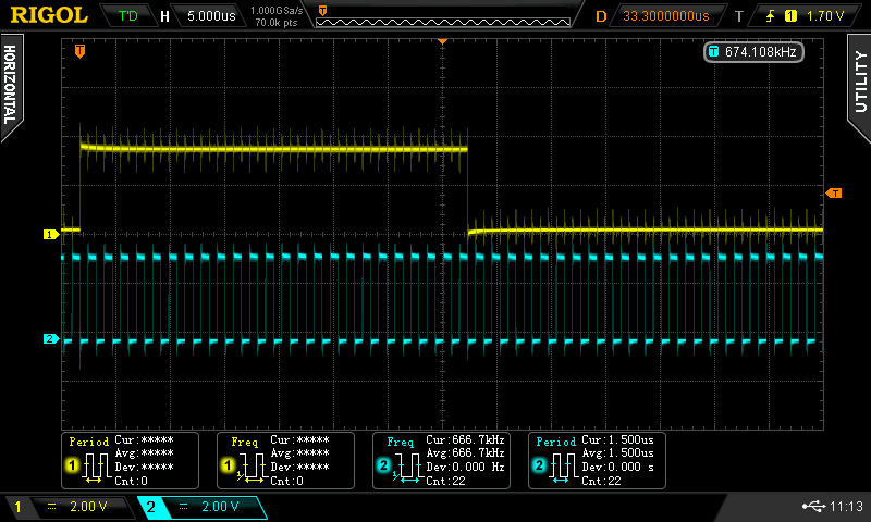
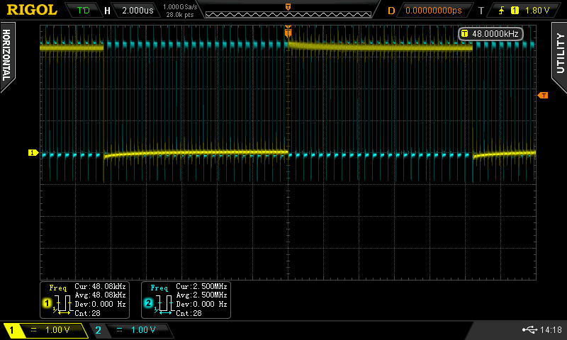
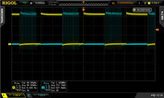
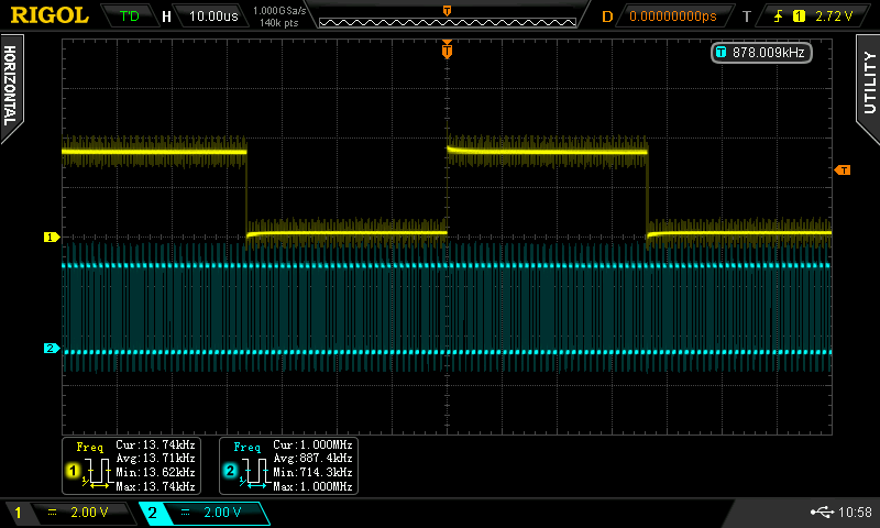
    I am still getting BTCLK of 666 khz. I attach a scope image.
    there are 48 btclk's in 1x FS cycle
    the mclk 12.288mhz supplied to the device is stable.
    mclk supplied on GPIO1 pin like this...
    // ***********  GPIO_CFG0 Register ***************

    // bit 7-4 = 1010  |  10d = GPIO1 is configured as a master clock input (MCLK)
    // bit   3 = 0     |  Reserved bit; write 0d
    // bit 2-0 = 000   | 0d = Hi - Z output , GPIO1 output drive configuration.

    // BIN 10100000 HEX = 0xA0
       
       ADC_I2C_Write(GPIO_CFG0, 0xA0);
    I will try and re-flow a new chip to the board today in case of this one was damaged and come back if there is any change.
  • Hi,

    I generated register values from Purepath 3 and I still get the slow BTCLK FSYNC

    How accurate does the the 12.288mhz mclk have to be ? does the PLL reject it if its not within a certain tolerance ? 

    here's the registers generated from purepath 3 ,  the forum upload wouldn't let me upload the project file


    // TLV320ADC3120 device configuration
    // -----------------------------------------------------------------------------
    // Reset
    // -----------------------------------------------------------------------------
    // Select Page 0
    { 0x00, 0x00 },
    // Reset Device
    { 0x01, 0x01 },
    // 1mS Delay
    // -----------------------------------------------------------------------------
    // Begin Device Memory
    // -----------------------------------------------------------------------------
    // Page 0 (0x00) Dump
    // Select Page 0
    { 0x00, 0x00 },
    // Wake up and Enable AREG
    { 0x02, 0x81 },
    { 0x05, 0x01 },
    // ASI configuration
    { 0x07, 0x60 },
    // ASI Channel configuration
    { 0x0c, 0x20 },
    { 0x0d, 0x02 },
    { 0x0e, 0x03 },
    // ASI master mode
    { 0x13, 0x81 },
    { 0x14, 0x43 },
    // GPIO Configuration
    { 0x21, 0xa0 },
    // Channel 1 configuration
    { 0x3c, 0x20 },
    { 0x3d, 0xa8 },
    // Channel 2 configuration
    { 0x41, 0x20 },
    { 0x42, 0xa8 },
    // DSP Configuration
    { 0x6b, 0x00 },
    { 0x6c, 0x48 },
    // input and output Configuration
    { 0x74, 0xc0 },
    // Power up/down
    // Select page 0
    { 0x00, 0x00 },
    { 0x75, 0x80 },

    };

  • Shall reply shortly

  • Hi Sanjay,

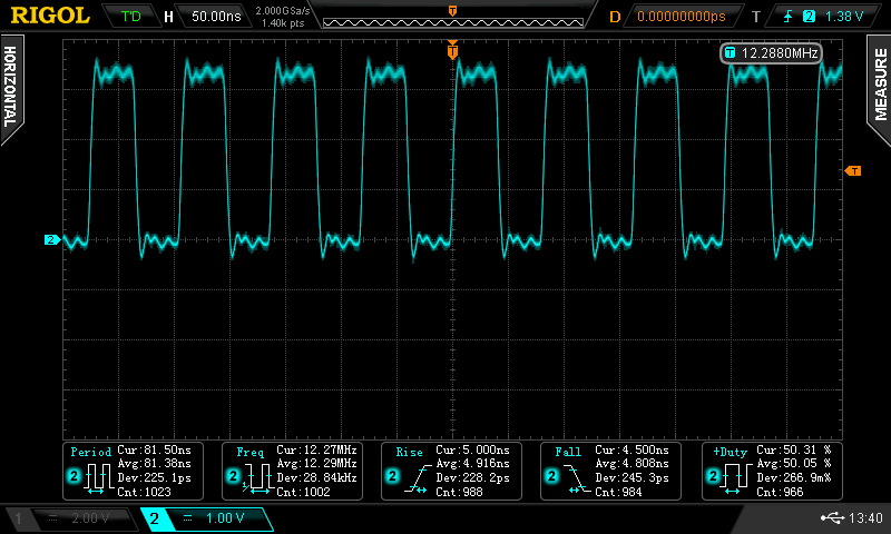
    I attached a screen capture of MCLK from the oscillator. Do you think it could be the problem?

  • The MCLK Looks OK.You could try placing a 33 ohm resistor in series with the source if possible,.

    Let me think a little and I shall send you a response tomorrow

  • I reflowed the chip one more time and now have good BTCLK and FSYNC.

    it must have just been a bad contact to one of the pins.

  • Hi Sanjay , apology's for the delay...

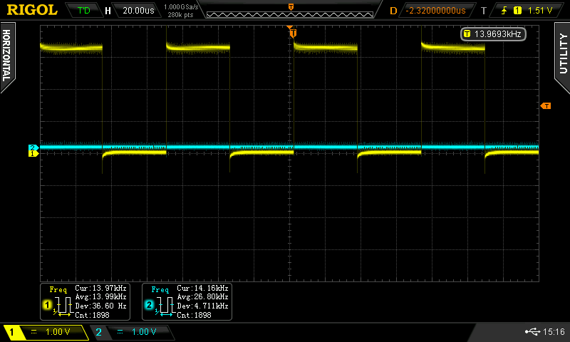
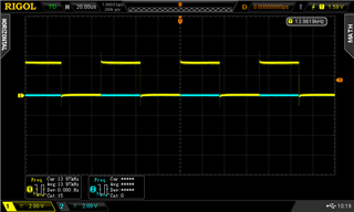
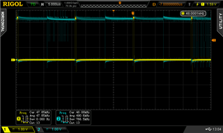
    I have tried your ADC setup registers and I get this on the scope.

    I added the power up register at the end w 98 75 E0

    should I be powering up PLL using your reg. settings?

    FSYNC = 13.976khz now and no SD data as in screen capture above.

    // # Select Page 0
    // w 98 00 00
    ADC_I2C_Write(0x00, 0x00);
    // # Reset Device
    // w 98 01 01
    ADC_I2C_Write(0x01, 0x01);
    // # 1mS Delay
    osDelay(1u);
    // # -----------------------------------------------------------------------------
    // # Begin Device Memory
    // # -----------------------------------------------------------------------------
    // # Page 0 (0x00) Dump

    // # Select Page 0
    // w 98 00 00
    ADC_I2C_Write(0x00, 0x00);
    // # Wake up and Enable AREG
    // w 98 02 81
    ADC_I2C_Write(0x02, 0x81);
    // w 98 05 01
    ADC_I2C_Write(0x05, 0x01);

    //# ASI configuration
    // w 98 07 70
    ADC_I2C_Write(0x07, 0x70);

    // # ASI Channel configuration
    // w 98 0c 20
    ADC_I2C_Write(0x0c, 0x20);
    // w 98 0d 00
    ADC_I2C_Write(0x0d, 0x00);
    // w 98 0e 00
    ADC_I2C_Write(0x0e, 0x00);

    // # ASI master mode
    // w 98 13 81
    ADC_I2C_Write(0x13, 0x81);
    // w 98 14 44
    ADC_I2C_Write(0x14, 0x44);

    // # PDM Configuration
    // w 98 1f 08
    ADC_I2C_Write(0x1f, 0x08);

    // # Channel 1 configuration
    // w 98 3c 20
    ADC_I2C_Write(0x3c, 0x20);

    //# Channel 2 configuration
    // w 98 41 20
    ADC_I2C_Write(0x41, 0x20);

    // # DSP Configuration
    // w 98 6c 48
    ADC_I2C_Write(0x6c, 0x48);

    // # input and output Configuration
    // w 98 74 c0
    ADC_I2C_Write(0x74, 0xc0);

    // # Page 1 (0x01) Dump
    // # Select Page 1
    // w 98 00 01
    ADC_I2C_Write(0x00, 0x01);

    // #VAD configurations
    // w 98 1e 00
    ADC_I2C_Write(0x1e, 0x00);
    // w 98 1f 00
    ADC_I2C_Write(0x1f, 0x00);


    // # Select Page 0
    // w 98 00 00
    ADC_I2C_Write(0x00, 0x00);

    // ************ PWR_CFG Power up the ADC, MICBIAS PLL etc Register Field Descriptions *****************

    // bit 7 = 1 | 1d = Power up MICBIAS
    // bit 6 = 1 | 1d = Power up all enabled ADC and PDM channels
    // bit 5 = 1 | 1d = Power up the PLL | 0d = Power OFF the PLL
    // bit 4 = 0 | 0d = Channel power-up, power-down is not supported if any channel recording is on
    // bits 3-2 = 00 | 0d = Channel 1 and channel 2 are used with dynamic channel power - up, power - down feature enabled
    // bit 1 = 0 | 0d = VAD is disabled , Enable voice activity detection (VAD) algorithm
    // bit 0 = 0 | reserved use 0
    //
    // BIN = 11100000 HEX = E0

    ADC_I2C_Write(PWR_CFG, 0xE0); // 0xE0 power ON everything including PLL

    // wait for adc
    osDelay(250u);

  • Would it be possibl to send me the file i sent you . I can't seem to find it.

    Also, after replacing the chip is the timing and data  correct?

  • Hi ,

    after chip replace using my reg setting I get 48khz 2.304mhz BTCLK.

    I get left SD data in I2S frame FSYNC low  , it does not sound correct coming out of the DAC ( TLV320DAC3203 )

    I don't get SD data in the right I2S frame when the FSYNC is high

    I should have say , in my last scope pic chan2 (blue ) is attached to adc SDOUT not btclk 

    your file contents and file attached

    # CHECKSUM 0
    # Generated by ADCx120EVM-SW v3.0.5
    # TLV320ADC3120 device configuration
    # -----------------------------------------------------------------------------
    # Reset
    # -----------------------------------------------------------------------------
    # Select Page 0
    w 98 00 00
    # Reset Device
    w 98 01 01
    # 1mS Delay
    # -----------------------------------------------------------------------------
    # Begin Device Memory
    # -----------------------------------------------------------------------------
    # Page 0 (0x00) Dump
    # Select Page 0
    w 98 00 00
    # Wake up and Enable AREG
    w 98 02 81
    w 98 05 01
    # ASI configuration
    w 98 07 70
    # ASI Channel configuration
    w 98 0c 20
    w 98 0d 00
    w 98 0e 00
    # ASI master mode
    w 98 13 81
    w 98 14 44
    # PDM Configuration
    w 98 1f 08
    # Channel 1 configuration
    w 98 3c 20
    # Channel 2 configuration
    w 98 41 20
    # DSP Configuration
    w 98 6c 48
    # input and output Configuration
    w 98 74 c0
    # Page 1 (0x01) Dump
    # Select Page 1
    w 98 00 01
    #VAD configurations
    w 98 1e 00
    w 98 1f 00

    3146.ben.cfg

  • i reply shortly

  • Hi Sanjay , any more thoughts on this ?

  • Hi Ben,

    I apologize for my delayed response here.

    To summarize you are getting a correct BCLK and FSYNC output after you changed the chip. But now the Data is appearing only when FSYNC is low.

    When you try to hear this data through a DAC is doeds not seem correct.

    Please connect a 1khz /0.5VRMS  differeential Signal through 1u capacitors to IN1P/IN1M and IN2P/IN2P.

    Please record the waveform on an Oscilloscope on DC Coupling and share with me. I would expect the signal on the pin to be riding on an internally generated by of 1.35v( For a  2.75V Vref)

  • Hi Sanjay,

    no worries regarding delayed response!

    I have found a problem on the input on channel 1.

    there is 1.35v bias on channel 2 if I measure before the 1uF blocking cap.

    I will go through the inputs circuit and see if there is problem with IN1M , maybe there is a short to ground

    somewhere on IN1M !!

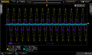
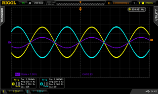
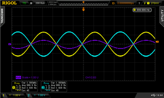
    Channel 1 : 0.5Vrms sign wave through 1uF cap 

    Channel 2 : 0.5Vrms sign wave through 1uF cap 

  • Hi Sanjay,

    My mistake , I left the Bias switched on.

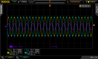
    both channels are ok on inputs in balanced mode and all inputs pre 1uF blocking cap are swinging around 1.35V center.

    Channel 1

    Channel 2

    I am using your reg settings on ADC with added 0x81 power on to switch all on. 

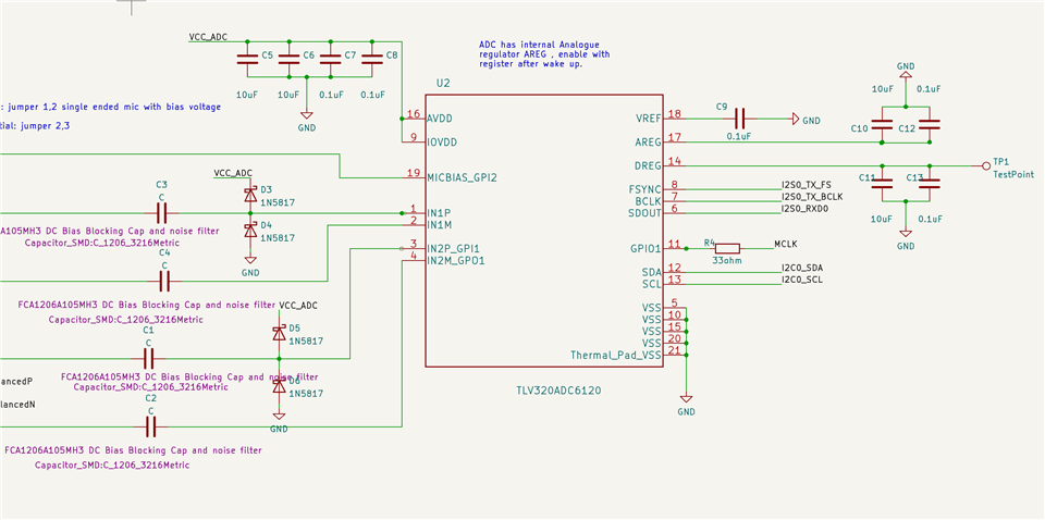
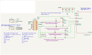
    This is the input schematic , the inputs are switched as in list on bottom left to balanced.

  • Great Ben. I am happy it works.

    best Regards

    Sanjay

  • Hi Sanjay,

    I am afraid although the balanced input circuit appears to be working I still have the original problem.

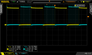
    your register settings produce this on LRCLK and SD

    my register settings with balanced audio inputs registers selected produces this. ( only one channel SD or possible both cannels on slot 0 of I2S )

    but at least I have the expected 48khz on LRCLK

    running out of ideas , anything else I can try ? 

  • I tired I2S LRCLK cycle length to 48 instead of 64 in case that was the issue but still only 1 channel SD data from ADC.

  • Shall respond shortly

  • Hi Sanjay,

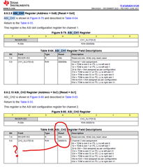
    Are the default reg settings in ASI_CH1 and ASI_CH2 registers good for 2 channel left / right I2S ?

    I tried writing both 0x00 and 0x01 to ASI_CH2 but still only SD in LRCK low ( left )

    I tried bit 3 ASI_CFG0  ASI FSYNC polarity.

    this put the single channel of serial data on FSYNC high ( LEFT )

    normally its on FSYNC low 

  • I tried TDM and I get data from channel 1 and 2

    unfortunately my MC SAI library only supports I2S and not TDM. 

  • # ASI configuration
    w 98 07 60
    # ASI Channel configuration
    w 98 0c 20
    w 98 0d 00
    w 98 0e 00
    # ASI master mode
    w 98 13 81
    w 98 14 44
    # PDM Configuration
    w 98 1f 08
    # Channel 1 configuration
    w 98 3c 20
    # Channel 2 configuration
    w 98 41 20
    # DSP Configuration
    w 98 6c 48
    # input and output Configuration
    w 98 74 c0
    # Page 1 (0x01) Dump
    # Select Page 1
    w 98 00 01
    #VAD configurations
    w 98 1e 00
    w 98 1f 00

    The settings above try to make I2S Dta on slot 0 Left and Slot 0 right

    Let me know if this helps. if not I shall try to generate your timings with an EVM Here.

  • Hi Sanjay,

    Unfortunately I get no BTCLK or FSYNC with these settings.

    I am using this for startup before your exported reg settings.

    /* ######################## ADC TLV320ADC6120 SETUP ############################## */


    // register pages

    // Page 0x00 normal setup registers ,
    // Page 0x01 VAD voice activity detection
    // Page 0x02 Programmable Coefficient Registers:
    // Page 0x03 Programmable Coefficient Registers:7 -12
    // Page 0x04 Mixer Settings

    /* go to page 0 */
    ADC_I2C_Write(PAGE_CFG, 0x00);


    // SW_RESET Register(Address = 0x1)[Reset = 0x0]
    ADC_I2C_Write(SW_RESET, 0x01);

    osDelay(20u); /* 10ms. */

    /* go to page 0 */
    ADC_I2C_Write(PAGE_CFG, 0x00);

    // Wake-up device by I2C write into P0_R2 using internal AREG

    // bit 7 = 1 | 1d = Internally generated 1.8 - V AREG supply using an on - chip regulator(use this setting when AVDD is 3.3 V)
    // bits 6-5 = 00 | Reserved bits; Write only reset values 0
    // bits 4-3 = 01 | 0d = VREF quick-charge duration of 3.5 ms (typical) | 3d = VREF quick-charge duration of 100 ms (typical)
    // bit 2 = 0 | 0d = I2C broadcast mode disabled
    // bit 1 = 0 | Reserved bit; Write 0
    // bit 0 = 1 | 1d = Device is NOT in sleep mode

    // BIN 10001001 HEX 0x81

    ADC_I2C_Write(SLEEP_CFG, 0x81);

    osDelay(1u); // 1ms.

    I write your reg values next.....

    /*
    *
    * # ASI configuration
    w 98 07 60
    # ASI Channel configuration
    w 98 0c 20
    w 98 0d 00
    w 98 0e 00
    # ASI master mode
    w 98 13 81
    w 98 14 44
    # PDM Configuration
    w 98 1f 08
    # Channel 1 configuration
    w 98 3c 20
    # Channel 2 configuration
    w 98 41 20
    # DSP Configuration
    w 98 6c 48
    # input and output Configuration
    w 98 74 c0
    # Page 1 (0x01) Dump
    # Select Page 1
    w 98 00 01
    #VAD configurations
    w 98 1e 00
    w 98 1f 00

    */

    Then I start the chip with.....


    // ************ PWR_CFG Power up the ADC, MICBIAS PLL etc Register Field Descriptions *****************

    // bit 7 = 1 | 1d = Power up MICBIAS
    // bit 6 = 1 | 1d = Power up all enabled ADC and PDM channels
    // bit 5 = 1 | 1d = Power up the PLL | 0d = Power OFF the PLL
    // bit 4 = 0 | 0d = Channel power-up, power-down is not supported if any channel recording is on
    // bits 3-2 = 00 | 0d = Channel 1 and channel 2 are used with dynamic channel power - up, power - down feature enabled
    // bit 1 = 0 | 0d = VAD is disabled , Enable voice activity detection (VAD) algorithm
    // bit 0 = 0 | reserved use 0
    //

    // BIN = 11100000 HEX = E0 // 0xE0 power ON everything including PLL

    // BIN = 01100000 HEX = 60 // no mic bias

    ADC_I2C_Write(PWR_CFG, 0x60);


    // wait for adc to power up
    osDelay(250u);

    It seams the PLL is not starting as I get no BTCLK at all.

    It looks like by default it should get my 12.288mhz clock from GPIO1

    Perhaps it would be useful if you could check your reg values with the EVM ?

    or maybe there is something I can do to check if the PLL is in fact running ? 

  • I shall try this out on an EVM. Please give me some time to arrange the setup

  • great , I think it will be helpful.

    if its working maybe you can tell me what voltages you see at AREG and DREG pins too.

  • i will let you know  the voltages i measure as soon as i get it up and running

  • Hi Sanjay ,

    Just wondered if you had any luck with the EVM ?

  • Hi Ben,

    I apologize VERY MUCH  I have not been able to take up this task due to ongoing activities. I shall try my best to take a look this week.

    Regards

    Sanjay