This thread has been locked.

If you have a related question, please click the "Ask a related question" button in the top right corner. The newly created question will be automatically linked to this question.

TAS5822M: Exported register map value and I2C read out is different.

Part Number: TAS5822M

Hi Team,

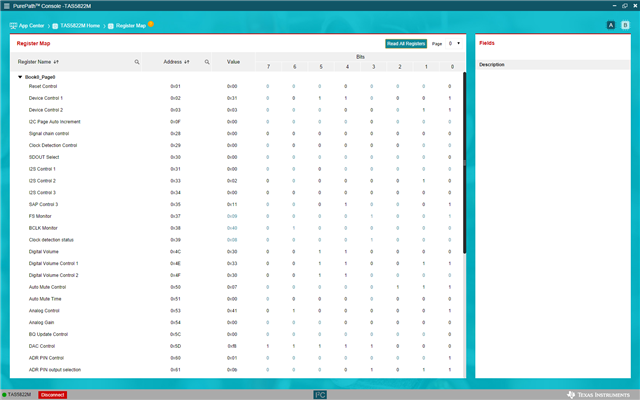
I have a customer who is looking at using TAS5822. They are currently facing issue with the exported register map value and the I2C read out( both read differently), even the initial start up before they do anything.

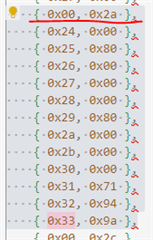
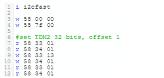
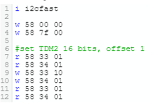
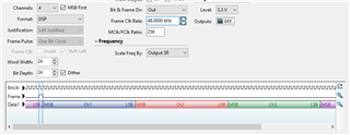
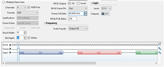
They tried to write some of the register thru the I2C, they can see the value are changed accordingly but when they try export the register map out and do a compare the value exported are different from what they have writen.

Could you please advise on this?

Thanks.

  • Hi Emest

       We may need details about it. Could you please let customer give us a specific register address the customer find issue. What is the value they read from it, and what is the value they expected to be. We could check it on the EVM. Thank you.

  • Hi Shadow,

    Thanks for your response.

    EndSystemIntegration.h

    Customer managed to damp the current state .h file and read some of the register out, the value are different, eg 0x33, 0x38 etc, may I check with you which is correct ?

    Also, customer need a Full set of register setting to initialize the chip to be set up as TDM audio decoder.  Could you help with that?

    Best Regards,

    Ernest

  • Hi Ernest

       I see, we have some misunderstanding on the dumped I2C codes.

       The PPC3 software Register Map is the correct value. But these register setting actually won't be dumped. The PPC3 will mainly dump the audio tuning related registers. All of the datasheet register, if we want to use different value from default, should added at the end of dumped codes.

       The dumped file, for example, we may think we write 0x9a into 0x33 register. But actually before these codes, there's (0x00, 0x2a), it means we changed to page 2a, and the register 0x33 is at page 2a, not the same with datasheet register.

       Most of the time the datasheet register could leave them as default settings. And for TMD, the datasheet chapter 7.3.6 has description of how to set it. Please let me know if you have any specific questions.

  • Hi Shadow,

    Thank you so much for your consistent support.

    However, TDM still DO NOT work at customer side, even they follow the recommendation in the spec.

     Can you help to provide us the correct setting if customer need a 4 channel TDM, for both 16 bits and 32 bits, 44.1KHz and 48KHz.  

    Is better you do a dump from you side and we will import it into our EVM to test it out

    Please kindly advise.

  • Hi Shadow,

    Happy new year, may I check with you if there is any update on this?

  • Hi Emest

       Sorry that somehow this Thread is missed in the system.

    Is better you do a dump from you side and we will import it into our EVM to test it out

       As I mentioned the dumped codes only contains the tuning related registers, to set the TDM, we have to set the registers according to the datasheet. It's only the register 33h and 34h need to set. Set bit [5:4] to TDM, b'01. Bit [3:2] need to set according customer's LRCLK. Bit [1:0] to choose the word length. Register 34h mainly to set the offset, customer could ignore it at first. 

        I suggest you to guide them use I2S format start PLAY firstly. If the device still can't work, there would be other problems, need to find out. Then changes to TDM format, and set the 33h registers. If you still have clock error, need to check the clock frequency and ratio, if they are within datasheet requirement.

  • Hi Shadow,

    Thank you so much.

    Yes we tried I2S by default 2 channel is working. 

    When set to TDM2, 24bits. Play audio track of 24 bits, 48KHz, Left Right channel is SWAPPED, but output at Right channel is distorted.


    This is what we set.


    So we try set to TDM2, 32bits. Play audio track of 24 bits, 48KHz, Left Right channel is SWAPPED, this time audio sound correct.


    This is the setting,

    And then we try set to TDM2, 16bits. Play audio track of 16 bits, 48KHz, Left Right channel still  SWAPPED, when we play mono, RIght channel only, the evaluation board shut down.


    This is the setting.


    Please kindly advise.

    Best Regards,

    Ernest

  • Hi Ernest

       We need to firstly make clear, the 16bit/24bit/32bit customer says, is the total length of every Slot, or it's the effective bit?

       Total length 24bit, should looks like below, and this is datasheet means. Every Slot has only 24bit and adjacent to each other.

       Only effective bit 24, could possibly looks like below. This is actually still 32bit Slot size, only for every Slot, used 24bit. From your description, they set 32bits and work normally with only swapped, it's quite possibly for this condition. 

       You need to make sure what is the SCLK and LRCLK frequency for each of the working conditions, test it with oscilloscope.

       Swap is not a big deal, simply swap the output cable or speaker. They either make mistake about the left/right channel from hardware like schematic or cable, or they make mistake to put correct left and right channel signal on the SDIN line.

  • Hi Shadow,

    Customer have already tried and swap is a big issue to them and it is causing the evaluation board to shut down. What customer needs is a full set of register setting to initialize the chip to be set up as TDM audio decoder. My understanding is that there should be some tables on the datasheet to configure this.

    Please kindly advise.

  • Hi Ernest

       As we discussed on the Webex, we need to make sure what is the TDM format customer is using. And the swap problem could be solved as I have suggested. You could send e-mail to our AE member Donny directly to solve this problem.