This thread has been locked.

If you have a related question, please click the "Ask a related question" button in the top right corner. The newly created question will be automatically linked to this question.

TPA3130D2: Calculation and Schematic Review

Part Number: TPA3130D2
Other Parts Discussed in Thread: TPS61088

Hello everyone,

For one of my University project, I need to build an audio amplifier to drive one speaker.

So far, I have chosen the TPA3130 because it seems to be a good candidate.

I’m asking for your expertise to review my calculation and check  my schematic.

See below context and input parameters of the project :

The audio signal will come from an ESP32 (DAC GPIO25).

There will be two ways of powering the board : 

  • 10V coming from a power supply.
  • 10V coming from a li-ion battery. (I think the TPS61088 could be a good a candidate to boost this li-ion voltage to 10V.)

The input is single ended and the device is in monomode (PBTL).

Settings :

Output power I want: 10W

Speaker impedance: 4Ω

Power supply: 10V

Voltage input (audio): 3.3V (coming from ESP32 DAC)

Calculation :

Output Power :

From figure 14, I assumed 10V is enough to output 10W. But the chart is given in BTL mode. So, value in PBTL is double?

Gain to set :

Po = [Vo(rms)]²/Rl → Vo = sqrt(10x4) → Vo = 6.32V

Vin(rms) = Vin(pp)/2sqrt(2) → 3.3V / 2sqrt(2) → Vin(rms) = 1.16V

G = Vin/Vo → 6.32/1.16 = 5.44 V/V → 20log(5.44) = 14.7dB

Estimated Consumption :

From the chart in the datasheet, the efficiency for 10W at 12V is 0.85.

Consumed Power = Output Power / Efficiency → Pc = 10/0.85 → Pc = 11.7W

Supply current = 11.7W / 10V Ia = 1.17A

In fact, since I’m using a 10V power supply, the consumption should be lower, right ?


There is my first draft of the schematic below:


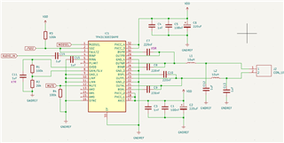
I still need to define the AM modulation, but I think this not a big issue.


Do you have any advice regarding the schematic and in the project in general?

Thanks for you help,
Sincerely,
Thomas.

  • Hi Thomas

       For the schematic, all the ceramic capacitor suggest to use X7R type, especially at BST and output filter. X5R's capacitance value may drop a lot when real working, the performance would be bad. And you may not want to float AM0/1/2 pins, connect them to GND if you needn't change it. 

    From figure 14, I assumed 10V is enough to output 10W. But the chart is given in BTL mode. So, value in PBTL is double?

    Only when BTL can't output enough current, the PBTL will takes effect and increase the max power. But for you using condition, the output power is limited by your supply voltage. The amplifier output voltage can't higher than supply, so you could get max 10V as peak sinewave output. On 4ohm load, you could get 12.5W. PBTL can't help here.

    In fact, since I’m using a 10V power supply, the consumption should be lower, right ?

    That's correct, your calculation seems no problem. Good work.

  • Hi Shadow,

    Apologise for the delay.

    Thank you for your feedback and informations Thumbsup

    I have another question regarding the gain. With R1 and R2, I have set the gain to 20dB.

    But with my calculation I found that I only need 14.7 dB. Will it cause some problem ? Like saturation or clipping ?

    To avoid that I could use a voltage divider or a potentiometer at the 'RINP' pin right ? 

    Thanks for your help,
    Sincerely,
    Thomas.

  • Hi Thomas

    Will it cause some problem ? Like saturation or clipping ?

    If you still gives maximum input level, the output will clip. You mentioned max input is 1.5V peak, 20dB Gain should get 15V peak output, but your supply voltage only 10V.

    Use resistor to divide the input signal should be the most simple way to solve problem. Give no more than 1V peak input.