This thread has been locked.

If you have a related question, please click the "Ask a related question" button in the top right corner. The newly created question will be automatically linked to this question.

PCM1865-Q1: Conversion from single ended to differential or differential and single ended connection selectable

Part Number: PCM1865-Q1
Other Parts Discussed in Thread: PCM1865, PGA2500, NE5532A, LM27762, TPS65133, PCM3168A

Hello IT team!

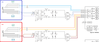
I'm working on a project where I need to multiplex the following X2 connections (so we can focus on only 4 of the 8 PCM1865 inputs):

  • MIC (DIFF) -> PGA2500 -> AntiAliasing Filter - PCM1865
  • TRS (DIFF)-> AntiAliasing Filter - PCM1865
  • TRS (Stereo (SE)) -> AntiAliasing Filter - PCM1865
  • TS (SE) -> AntiAliasing Filter - PCM1865

The following doubts have arisen:

  1. Considering that the PCM1865 has internal PGAs, is there any benefit to previously converting a single-ended signal (from stereo TRS or TS SE) to differential using NE5532A? To consider, if I perform a conversion, perhaps those lines need to go through a multiplexer analog (MAX14662)
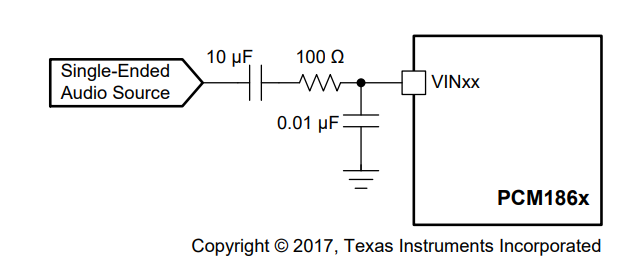
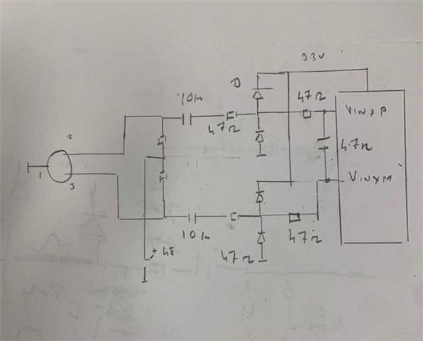
  2. I can configure VINL1/VIN1P and VINL2/VIN1M according to "Figure 63. Differential Input Circuit With Additional AntiAliasing Filter" and toggle between a differential assignment example: ADC1L (bit 0-5 -> 01 0000: {VIN1P, VIN1M}[DIFF]) from Register 6 (address = 0x06) to two single ended assignments example: ADC1L (Register 6) (bit 0-5 -> 00 0001: VINL1[SE] (default)) and ADC2L (Register 8) (bit 0-5 - > 00 0001: VINL1[SE] (default))? I ask because the datasheet recommends a resistance of 100 ohms for the filter and the capacitor to ground in an SE connection while in a differential the resistance is 47 and the capacitor is between the lines.
  3. I see that the L and R channel multiplexer allows any of its two ADCs to be diverted, what happens if I divert the same line (example: VINL1/VIN1P) to ADC1L and ADC2L?

Additionally, I would appreciate if you could help me with other questions outside of this context:

  1. Which regulator inverter is best to power HiFi audio AFE circuits such as the PGA2500 or the NE5532A, the LM27762 or the TPS65133? I have not found a PSRR graph on the TPS65133.
  2. Is there a possibility that you can unify the TDM signals from the output of the PCM1865 and a PCM3168A in the same way that two PCM1865 can do to generate a 10-channel TDM?


I appreciate your response in advance.

  • I would suggest to place the below circuit on all the lines

    Once you do so you can switch over from single ended to differential in the software.

    -------------------

    While I do not understand you full system requirement properly , in my opinion a single ended input can be given to the ADC and any Gain can be achieved in the ADC . An external OP Amp is not required.

    Sometimes people prefer differential signals as the traces may be travelling long distances and an ability to reject external noise is needed .This rejection of noise can be done by a differential system. if there is no such requirement a  single ended signal is fine.

    -------------------------------------------

    I apologize I could not understand the below question clearly. Can you please explain furthur?

    1. I see that the L and R channel multiplexer allows any of its two ADCs to be diverted, what happens if I divert the same line (example: VINL1/VIN1P) to ADC1L and ADC2L?

    -----------------------------------------------

    Both converters operate at 2Mhz and produce swiching noise. We need to make sure that the High current switching circuits are kept seperate from the analog grounds of the op amps/PGA. This will ensure good performance with either device.

    Also i note that LM device has an Internal low Drop LDO. This does not seem to be present in the TPS Device. For this reason the LM device may be a good choice.

    The TPS Device can provide more power.

  • Thank you for responding so promptly, Sanjay, and sorry if my questions weren't clear enough. Allow me to address them better.

    What I need is to connect two XLR/TRS combo connectors to the PCM1865. In the image, you can see a simplified diagram of how I intended to do it.


    VIN3/4P and VIN3/4M will be connected to an LPF, and this, in turn, to the PGA2500. The other two pairs (T/R) would be connected to VIN1/2P and VIN1/2M, passing through an LPF beforehand.

    Each XLR/TRS connector has its own PCB, and it, in turn, connects to an AFE Board, where the PGA2500 or the PCM1865 is at most 10cm away. Our priority is the audio signal quality, but we understand that there may be a compromise between cost, complexity, and quality. I understand that differential routing has benefits in signal integrity, SNR, and Common Mode Rejection.

    Considering that the PCM1865 has its own AO for each ADC, and these convert differential and single-ended signals to full differential for the ADC (Figure 26. Internal Block Diagram of the PCM186x-Q1), I considered it unnecessary to add several AO and switches to the preamp, something I had to do with a PCM3168A.

    If the internal PGAs are suitable for connection via an LPF to the outside and if the conversion of a single-ended signal to differential by these PGAs is better than what a [NE5532A + Switch + DIF to DIF to PGA] would do, then I will use only the PCM1865 + LPF as AFE, since the NE5532A cannot be placed closer to the connector than the ADC can.

    Clarifying my 3rd question:

    My question is if the MIX/MUX can route one channel to two ADCs (L1 and L2), and if I can route two channels to one ADC (I calculate that it is possible, and that this is the analog MUX function).

    Regarding your answers:

    To conclude, thank you for suggesting the connection in Figure 61. Could you explain to me the implications of changing the resistance from 47 to 100 and the capacitor to ground instead of between lines in case the selection is unbalanced? Or do you propose it because, of the two options, it's the less bad one?

    About the TPS and the LM, I agree that having the built-in LDO is an advantage, but it raised a doubt when you say that the TPS supports more power. As far as I saw, both can provide 5V, but the LM has a maximum output of 300mA.

    Last question:

    Is there a possibility that I can unify the TDM signals from the output of a PCM1865 and a PCM3168A in the same way that two PCM1865s can to generate a 10 channel TDM?


  • Lets try to look at it one issue at a time.

    You could 'Perhaps' connect the Mic direct to the ADC without using the PGA2500. Here we need to make sure that the input pin voltage on the ADC does not go above AVDD+0.3 v or below -0.3V . At these levels input protection diodes turn on and the current should be limited to less then 5ma into these diodes.

    Assuming there are no protection diodes externally

    The input Coupling Capacitor has a Voltage of almost 48V on it. On powerup when the coupling cap is short a current of 48v/6k8 or 7ma can flow into the protection diodes into the pin for a short time

    When 48v is switched off a negative current of 7ma will flow into the protection diode of the chip.

    We place external diodes to carry this  current. We also place a second 47 ohm resistor to the pin . This ensures that the current flows into the first diode.

    The RC Filter should have a net R=100 ohm and C=10n.

    For a differential connection the 100 ohm can be split as 47 ohms on each of the 2 lines. In our example we have a total resistance of 200 ohm so we keep the effective time constant same as before by reducing C to 4.7n.

    With these values there is hardly any signal loss and noise performance should also be good.

    The PGA 2500 Has a DC Servo that improves the CMRR . This is an additional feature . However i feel that the PCM186X has a CMRR of 56db which is also good.

    --------------------------

    One question: I dont see a single ended input in your circuit.I am not fully clear on how you wish to connect this.

  • Sanjay, thank you for responding again and taking the time to outline a schematic.

    The decision to add a PGA2500 to our configuration was not only for CMRR but also to have the capability to accept dynamic and condenser microphones ranging from low to high sensitivity (-60dBV to -30dBV). The internal PGA of the PCM1865 is not sufficient for this.

    Addressing your design, I find a discrepancy in your statement and what the datasheet says regarding the current flowing through the diodes. Is this correct and does it correspond to the specific configuration you have implemented?

    "To protect the PGA2500 from large surge currents, power Schottky diodes are placed on the input pins to both the VA+ and VA− power supplies. Schottky diodes are used due to their lower turn-on voltage compared to standard rectifier diodes. Power devices are required since the surge currents from a large-valued blocking capacitor (47µF) can exceed 4.5 amps for a very short duration of time. It is recommended that the Schottky diode chosen for this application be specified for at least a 10A surge current."

    Answering your question, the single-ended input will be selected by software on the R/T lines of each connector, with one case where R is GND (TS plug connected = unbalanced mono audio), another where both R and T are assigned to an ADC (ADCL1 and ADCL2 for the CH1 connector) to treat the signal as two unbalanced channels, and lastly, considering R/T as differential lines for a balanced channel.

    In essence, the software will determine how the TRS input will behave, whether as a single unbalanced channel, a double channel (or stereo if preferred) unbalanced, or a single balanced channel.

    I hope this is clear; otherwise, I am here to address any doubts.

    Thank you very much.

  • I proposed the schematic with a view that the PGA2500 could be removed, However since the PGA2500 is needed in your application for a greater sensitivity i guess this schematic would not be used.

    In my schematic, to my understanding The Bias Resistor to the 48v is always present in series with the capacitor during the Power on and Power off of the 48 V. Assume t=0+ time when the capacitor has zero Volts across it a Current of (48-Va)/R flows through the diode. With R being a Kilo- ohm value the current is not very large and in the milliamp range.

    I just looked at the PGA2500 Schematic and this has a bridging resistor . Perhaps this changes the situation during turn off of the 48V.

    I am not directly supporting this PGA2500 so my understanding is based on common sense reasoning on the schematic. I apologize if i am mistaken here.

    -------------

    If the TRS input is to be used as a differential/Single ended mode then i think RC Filter of 100 ohm and 10n on each line shall work for both cases