This thread has been locked.

If you have a related question, please click the "Ask a related question" button in the top right corner. The newly created question will be automatically linked to this question.

OPA1612: Question about phase margin of circuit(PCM1794A - Reference simulation TINA)

Part Number: OPA1612
Other Parts Discussed in Thread: PCM1794A

Hello Mr or Mrs.

Happy new year~!I am always grateful for your help. :)

I am designing a circuit which is related DAC output and it  confuses me.

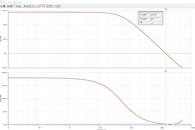
This is a PCM1794a reference TINA simulation design and bode plot.
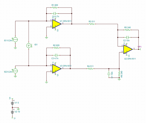
It looks two stages that first I/V conversion and filter with summation.

I heard lack of phase margin can cause oscillating problem thus over 45 deg of phase margin is required.

In the reference simulation, however, it looks lack of phase margin.(3 deg?)

The reason why I ask you this question is that I am struggling for phase margin.

This is my simulation design. 
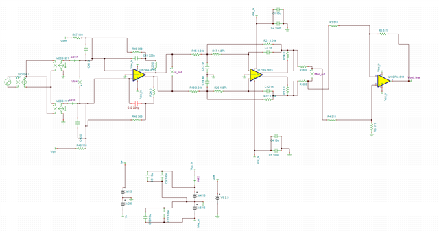
DAC output current: +- 18.2mA

Filter topology: MFB (fc: 32140Hz) - TI filter pro 2nd LPF and mirror for FDA.

Vcc Vee: +-15V

INPUT: Sine wave generator. 

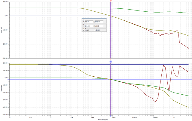
After LPF stage, It looses phase margin(Actually unstable).

I just wonder....

1. I don't have to worry about the point where the gain is 0db outside the frequency range I'm interested in(10 ~ 22kHz)

2.  Should input and output be considered for each stage? (  Input vs output of I/V, LPF, or Balanced to Single stage) 

3. My circuit design is wrong...

I attached TSC file. 

test_DAC_E2E.TSC

Please give me a advice.

  • Hi Jung,

    Happy New Year!

    You are correct that a phase margin >45° is desirable for closed loop stability, and to prevent the output from oscillating. However, the bode plot you generated is showing the phase of the output voltage relative to the input signal. This is not the same as phase margin. Phase margin measures how close (in degrees) the phase shift of AOL*Beta is from 0 degrees. The TI Precision Labs video series on op-amp stability explains in detail how to determine the phase margin by simulating the open-loop gain (AOL), and the feedback factor (Beta) by breaking the feedback loop. See the TIPL Stability Series - Phase Margin video and the remaining 7 videos in the series for more information.

    Setting up the AOL and Beta simulations can be difficult and time consuming, especially for a larger and complicated circuit. A quick and indirect way to determine the phase margin and access the circuit's stability is by measuring the overshoot of a small-signal step response. If the percent overshoot is less than ~22%, the phase margin is greater than 45°. 

    Op Amps Stability - Amplifiers forum - Amplifiers - TI E2E support forums

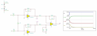
    I simulated this in the circuit shown and there is essentially no overshoot at all in the step response. This means that the phase margin is very good likely near 90° and there is no concern for stability or oscillations.

    OPA1612_Differential_TIA.TSC

    Regards,

    Zach