This thread has been locked.

If you have a related question, please click the "Ask a related question" button in the top right corner. The newly created question will be automatically linked to this question.

DRV2700EVM-HV500: I have many questions about DRV2700EVM-HV500

Part Number: DRV2700EVM-HV500


Hello, I'm Jeon Hyeon Min

Although I read DRV2700EVM-HV500 User's guide so many time, I don't understand how to use DRV2700EVM-HV500.

Here's my questions.

1. I'm using piezoelectric actuator which has 0.8 uF. When I connect actuator to DRV2700EVM-HV500, 100Hz output looks strange. See the picture below

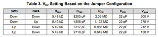
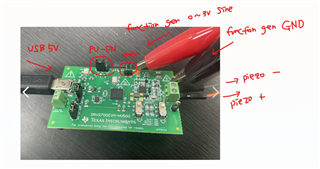
SW3, SW4 are stay up to limit 158V, analog input to TP1 and ground to GND, computer is connected to DRV2700EVM-HV500 using USB.

Is there any wrong in setting?

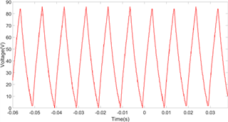
2. When I insert USB to computer to supply 5V to DRV2700EVM-HV500, I can see 158V DC output through oscilloscope. Load is an capacitor which has 0.33uF. Output voltage is shown in the picture below.

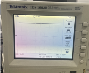
Next, I connect function generator to TP1 and GND, turn on function generator(0~3V, 1Hz) and the result is shown in the picture below.

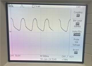
Is the response normal?

I don't understand DRV2700EVM-HV500's mechanism.

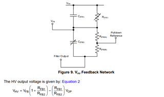
In User's guide(picture below), 0~3.3V 100Hz sine function analog input is blue graph and capacitor load is 22nF. so the result is green graph right?

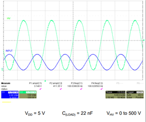
What should I do to see that clean green graph?

  • Hello,

    Thanks for reaching out.

    For the first case (0.8uF at 100Hz), I believe this is the expected response for the load capacitance and input frequency combination. Can you see if decreasing the frequency here yields an improved waveform? 

    For the second case (0.33uF at 1Hz), this will require more inspecting on my end. It does not seem like a frequency dependent issue, but I am curious if you get this same response if you vary the frequency?

    Regards,
    Sydney Northcutt 

  • Thank you for your reply!

    First, If I decrease frequency at 0.8uF at 100Hz, I can get improved waveform. but the problem is, I want to drive piezo actuator over >100Hz. Is there any other way but to use a piezo actuator with a lower capacitance?

    Second, I want to amplify 0~3V AC sine waveform to 0~150V AC sine waveform ( average : 75V, peak to peak : 0 to 150 sine wave). So, how do I calculate the output voltage for the input analog voltage signal? I think the pictiue below (section 4.1) shows how to calculate the output voltage for the input analog signal, isn't it?

    And the table below is each part's electrical properties

    In my case, SW3 and SW4 stay "UP" so maximum output voltage is 158V.

    So, the R_FB_2 = 5.49 k ohm , C_FB_2=2710 p Farad, R_FB_1 = 0.642 M ohm, C_FB_1 = 22 p Farad.

    Then, How do I calculate the V_HV when the load is 0.8uF?

    I'm sorry that the quality of explanation is low due to my lack of knowledge about electric and electronic :( 

    Thanks.

  • Hello,

    I believe this is the result of increasing frequency with a high capacitance as the cap has less time to charge / discharge. I don't believe there is a way to fix this response other than using a load with lower capacitance.

    The output voltage is calculated by the Equation 2 in the image you provided. To calculate the output with your load, you will have to consider the charging / discharging timing characteristics of your load.

    Regards,
    Sydney Northcutt