


Hey,
I am trying to use the TLV320ADC6120 to sample a PDM MEMS microphone.
The adc is configured via I2C and its output is read via I2S using an ESP32C6. I am using a PDM breakout board (https://learn.adafruit.com/adafruit-pdm-microphone-breakout) to generate PDM-data.
The breakout board is connected as follows:
DATA------IN2P_GPI1
CLK-------IN2M_GPO1
SELECT----GND
GND-------GND
3V--------Vin
These are the settings sent via I2C (there is no NAK) after powering up:
// wait for 1ms
h4E WR h00 h00 // select page 0
h4E WR h02 h81 // SLEEP_CFG := SLEEP_CFG_DEFAULT | SLEEP_CFG_AREG_SELECT_INTERNAL | SLEEP_CFG_SLEEP_ENZ_ACTIVE
// wait for 1ms
h4E WR h00 h00 // select page 0
h4E WR h07 h70 // ASI_CFG0 := ASI_CFG0_DEFAULT | ASI_CFG0_FORMAT_I2S
// (the breakout board has no capacitor between data and GPI1, so we need to use CH1_CFG0_DC_DC
h4E WR h3C h50 // CH1_CFG0 := CH1_CFG0_DEFAULT | CH1_CFG0_INSRC_PDM | CH2_CFG0_INSRC_PDM | CH1_CFG0_DC_DC
h4E WR h22 h41 // GPO_CFG0 := GPO_CFG0_DEFAULT | GPO_CFG0_GPO1_CFG_PDMCLK | GPO_CFG0_GPO1_DRV_ACTLOW_ACTHIGH
// actually this is not required but should not change anything
h4E WR h21 h63 // GPIO_CFG0 := GPIO_CFG0_DEFAULT | GPIO_CFG0_GPIO1_CFG_PDMCLK | GPIO_CFG0_GPIO1_DRV_ACTLOW_ACTHIGH
// CH2 shouldn't be required
h4E WR h2B h45 // GPI_CFG0 := GPI_CFG0_DEFAULT | GPI_CFG0_GPI1_CFG_PDMDIN1 | GPI_CFG0_GPI2_CFG_PDMDIN2
h4E WR h73 hF0 // IN_CH_EN := IN_CH_EN_CH1_ENABLED | IN_CH_EN_CH2_ENABLED | IN_CH_EN_CH3_ENABLED | IN_CH_EN_CH4_ENABLED
h4E WR h74 hC0 // ASI_OUT_CH_EN := ASI_OUT_CH_EN_CH1_ENABLED | ASI_OUT_CH_EN_CH2_ENABLED
// wait for 1ms
h4E WR h00 h00 // select page 0
h4E WR h75 h60 // PWR_CFG := PWR_CFG_DEFAULT | PWR_CFG_ADC_PDZ_ON | PWR_CFG_PLL_PDZ_ON
Afterwards the clock is running with about 2.8MHz on GPO1.
The problem is that Data does not seem to contain any useful data. I only receive noise but no sound. I also have to use a high gain to see any signal at all.
Interestingly, the Data-signal looks similar if the mic is not powered at all.
Loud sounds (e.g. a clapping near the microphone) are visible in the audio-signal, even if you do not recognize them when listening to the recorded audio. It rather looks like a single oscillation.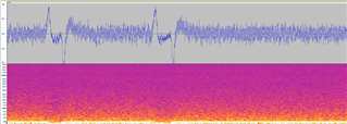
If the adc is configured to sample analog signals, it is working properly, so I guess that there is a problem with my configuration process.
Since I2C and I2S are working properly when sampling an anlog microphone, there shouldn't be a problem.
Do you have any ideas why I do not receive any useful data via I2S? Am I missing some required parameters in my configuration?
Thank you in advance

