Part Number: TAC5212EVM-K
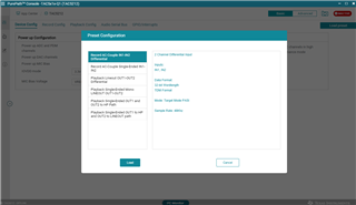
I recently received one of your evaluation boards and am finding the documentation a bit hard to follow. I was wondering if you might be able to suggest an initial set of configurations that I can use to do a basic loopback test.
I installed your software to let it activate the hardware, and am able to use it as an audio device (microphone) to record audio. So far it is just noise, but the jumpers tentatively seem okay in the default positions. I need to look closer, but if you have suggestions for getting a specific coaxial port (top or bottom, they aren't labeled super clearly to me) wired up to be either AC or DC coupled to an ADC I can test it with a signal generator properly. I'm just not sure why I see no sign of life while the device is active (I did power up the ADC).
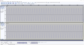
I installed Audacity to let me generate tones and record audio while playing them. I connected OUT1 (P?) to IN1 (P?) and tried to play 440Hz while recording and that just showed the same noise. I connected OUT1 up to an oscilloscope in single-ended stereo mode and it seems like a clipped waveform with a heavy discontinuity which doesn't change as volume shifts. I thought I had the jumpers okay, but it's definitely a little tricky.
Right now, honestly all I want to do is a loopback test and then to be able to measure the harmonic distortion accurately on my precision instruments to validate the performance. Is there a simple set of jumper configurations that would let me just output stereo audio and make one of these coaxial ports the left channel? I can switch to differential output to get a more fair distortion measurement once I get it to work at all...
Thanks! I'm very excited about the performance this will have and am looking forward to characterizing it.