This thread has been locked.

If you have a related question, please click the "Ask a related question" button in the top right corner. The newly created question will be automatically linked to this question.

TAS5805MEVM: EVM is not working

Part Number: TAS5805MEVM
Other Parts Discussed in Thread: TAS5805, TAS5805M

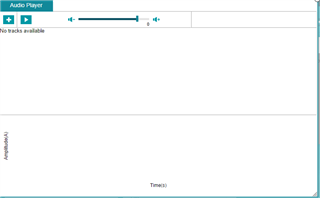
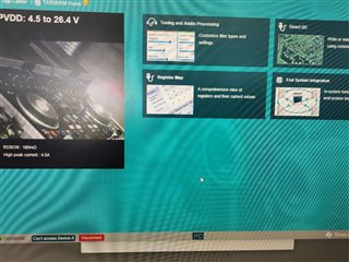
The EVM board can be connected successfully, but adding audio in the AUDIO PLAYER is unsuccessful. Also, when playing audio on the PC, the TAS5805 EVM board has no signal output.

The connection to the EVM board (IIC) is successful; however, the media player on the computer freezes up.

How can I solve this problem? Is there a fault with the EVM board? Thank you.


  • Hi 

       I suggest to do following check:

      1. Check if TAS5805 is succesfully into PLAY mode. Could check register 0x68, or test direcly at OUT pin to find the PWM waveform.

      2. Could use Windows media player direcly, needn't to use PPC3 player. And check the Speaker selecion in your computer, to choose USB.

      3. The switch on the EVM should select XMOS.

  • 1. Checked that there were no PWM waves on the output pins

    2.When the PC successfully connects to the EVM board (IIC connection successful), the Windows media player cannot play either.

    3.The switch on the EVM  XMOS.

  • Hello,


    In your windows sounds settings on your PC are you seeing the TI USB Audio 2.0 as options in the Output and Input settings? One such app that may be useful for audio playback that is commonly used is Audacity, it's a free software that can play any audio files and allow you to select the output and input for audio playback.


    best regards,

    Luis

  • If so, the problem still cannot be solved, which may indicate a fault in the DEMO board. How can we repair the EVM board?

  • Hi

    which may indicate a fault in the DEMO board. How can we repair the EVM board?

    Please check if the board could be successfully connect with your PC, after PVDD supply provided. If could connect, usually the board is no big problem.

  • t cannot be connected as shown in the picture.。

  • Can you give me a definite answer? I have tried all possible operations. I think the EVM board is broken. Can I send it back to you for troubleshooting? We have been communicating directly for two weeks, but you haven't helped me solve the problem.

  • Hi

      The device A is the upper side TAS5805M, you could check if the DVDD jumper correctly on it, or the address resistor is no problem on the board. Below link is the EVM User Guide, for you to do some debug.

      And is it a new board been applied from TI? Also some possibility the TAS5805M device has some problem, if you have IC, could consider change it.

    www.ti.com/.../slou510.pdf

  • I am also a technical engineer, and I have checked all possible issues. It is confirmed that the main chip is broken. I hope I can send it back to you for repair. Please don't always give me uncertain reasons. This is a waste of our time. Now I hope to confirm sending it back to you for repair

  • I would like to ask, you haven't received my EVM board yet, and you are just making guesses. This is a very irresponsible response. You can just write a sentence or two, but I have to wait for a whole day for your email. How can I make a complaint to your senior management? It has been two weeks, and I still haven't received a definite answer. This is not helpful at all

  • We have definitely checked these simple voltage parameters ourselves and ruled out any obvious issues. It's only after trying these basic steps that we decided to contact you. Now, the problem is that we can't solve it ourselves, so we're looking for your help. Is it so difficult for you to provide a clear answer?

  • If your technical ability is not sufficient, could you please arrange for a more experienced and capable engineer to respond to me? We don't want to waste any more time

  • Hi 

      Since you are quite confident about the issue, please go ahead to change the IC on the board.

  • We are also experienced engineers. We are sure that the problem is not with TAS5805, and if it were, we would have replaced it long ago. We have confirmed that the main chip XEF216-512-TQ128-C20 is broken, which is related to program control. However, we do not have this IC (XEF216-512-TQ128-C20). Therefore, we have been hoping that you can help us with the repair. We have also searched for all possible solutions and materials on your official website (PPC3 quick reference, slaa701a, slaa836, slaa880, slaa894, slla437, sloa263a, slou408 [PPC3 User Manual], slou510), but none of them have been successful. We hope that you can confirm whether the board is broken. A "yes" or "no" response is needed. Only if you confirm the issue, can we proceed to send the EVM board to you for repair. We also confirm that we do not have the ability to perform the repair ourselves.

  • Hi

     I'm afraid XEF216-512-TQ128-C20 is not TI's device. And additionally, when this device is broken, it can't connect with PPC3 software, there's no "Connect" button at all. Not just saying "Can't access Device A". Also there wont' be I2S clock generated from XMOS side, not sure if you have tested the clock or not.

      This device is just used for transfer USB into I2C control, also generate I2S clock. If you still sure this device is the problem, on the board, there's still SPDIF could generate I2S, you just need some way to send I2C. Usually could consider using another EVM to jump SCL and SDA line.

  • We have confirmed that the IC (XEF216-512-TQ128-C20) is faulty, which indicates that the IC is not working properly, including the IIS signal. I confirm with you again that all the drawings for the SLOU510 document have been tested.

    1: Each branch voltage in the circuit corresponds to the EVM board. This confirms that the power supply is good.

    2: The function of each pin of U18 (TCA6408ARGTR) and the output waveform have been tested and confirmed. As shown in the following figure

    3. Test the functions of each pin of U15 (CDCE913PWR) and confirm the output waveform (BCLK-XMOS; MCLK-XMOS). As shown in the following figure

    4.测试U12(XEF216-512-TQ128-C20),输出波形(LRCLK-XMOS;BCLK-XMOS),也是确认是没有波形。所以我们判断它损坏了,现在我们没有能力去维修这部分。如下图

    We are also experienced electronic engineers, and we have tried our best to investigate the issues that can be considered. We need your confirmation now to confirm that this EVM board is damaged. So we can go to your repair department and ask them to help us repair it. We have been communicating with you for 3 weeks now. Our company cannot afford this time loss. I hope you can confirm that this EVM board is broken based on your responsibility for work and technology. thanks

  • Hi

      If you can't test I2S clock at below position, then indeed quite possible the XMOS device has some problem.