Because of the holidays, TI E2E™ design support forum responses will be delayed from Dec. 25 through Jan. 2. Thank you for your patience.

This thread has been locked.

If you have a related question, please click the "Ask a related question" button in the top right corner. The newly created question will be automatically linked to this question.

TLV320AIC3204: How to use PDM input as briefly shown in doc SLOS602E page 20

Part Number: TLV320AIC3204
Other Parts Discussed in Thread: PCMD3140

Hi all,

I got myself a test kit for a PDM microphone from Knowles and it works well with their dev kit which is just a USB dongle with an application. What I would now like to do is to get the PDM audio and convert it either to a PCM bitstream or an analog output.

On the TLV320AIC3204, I found in document SLOS602E –SEPTEMBER 2008–REVISED SEPTEMBER 2019 at page 20 (section 7.16 Digital Microphone PDM Timing) a small graph showing PDM timing but that's it, there's no other details on how to use this feature.

Is there any kind of information for this particular IC (because I have it already on some circuits) that I could obtain in order to accomplish what I am trying to achieve?

Who can assist on this? How can I input the PDM data into the CODEC so that I can have it converted through the CODEC then routed out an analog output (but preferrably as a raw 16-bit 16kHz or 8-bit 8kHz bitstream)?

Thanks,

Ben

  • Hi Ben,

    The application reference guide (Section 2.3.3.2.2) has better detail on setting up digital mic support: https://www.ti.com/lit/ml/slaa557/slaa557.pdf?ts=1710875946480&ref_url=https%253A%252F%252Fwww.ti.com%252Fproduct%252FTLV320AIC3204

    Section 2.3.3.3 will walk you through the whole ADC set up. Once set up correctly, you can get the data from the mic in a 16bit form like you want as well as enable a loopback to play it through the DAC, though this also requires setting up the DAC side.

    If you're only interested in a digital mic to I2S conversion (no analog out) I encourage you to check out the PCMD3140: https://www.ti.com/product/PCMD3140?keyMatch=PCMD3140&tisearch=search-everything&usecase=GPN-ALT

    It's cheaper than the codec and the software support is much friendlier.

    Best regards,
    Jeff McPherson

  • Hi Jeff,

    Thanks for the fast response. I had already looked at the PCMD3140 but I am not equiped to do soldering that small. I am just testing out this microphone I was handed. I guess I could always order the development board.

    As for the section you mention 2.3.3.2.2, I will look into it tomorrow.

    I will update this ticket when I have a chance to test it.

    Thanks!

    Benoit

  • Hi Benoit,

    Ok, let me know if you have any further questions,
    Jeff McPherson

  • Hi again Jeff,

    I've read through the section 2.3.3.3 and pardon my ignorance but I have no clue how to configure the CODEC to go from PDM in to I2S out (or analog out) in a sense that I don't see any explicite explanation like "To convert a PDM input to xxx output, do this". I just discovered what PDM was two days ago with a dev kit that is meant to test a PDM-out microphone that goes to my PC over USB for testing.

    My AIC3204 CODEC is currently configured to get its MCLK of 3.072MHz and BLCK of 128kHz from a PIC24 MCU as PWM signals 50% duty. I cannot go any faster than 3.072MHz for the MCLK. In return, the CODEC returns an 8kHz WCLK as well as the PCM audio data of 8-bit 8kHz on DOUT.

    As explained, I'd like to try to route the PDM audio to one of the analog outputs but also, get it as PCM 16-bit 16kHz output and even 8-bit 8kHz output.

    All this to say that as far as the PDM to whatever conversion from the section you provided goes, I honestly have no clue how to to go about.

    Is there a known working register setup example I can follow?

    Thanks again,

    Benoit

  • Hi Benoit,

    I'm lacking the hardware at the moment to write a configuration example, but I can more clearly define the steps:

    1) Determine where the PDM clock output should come from (either GPIO (Register 52) or MISO (Register 55)).

    2) Determine where the PDM data should be input to. Simplest option is DIN using Register 54.

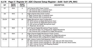
    3) In Register 81 reflect the settings you configured in step 2: Where is the data coming from. In the same register you'll need to set either or both of the ADCs to digital microphone input. Apps reference guide says analog portions can be powered down, but let's just leave the ADC on for now.

    4) Unmute the ADC with register 82. You can refer to steps in section 4.0.4 in the apps reference guide for setting up the ADC path. Things like PGA settings won't apply since those are for analog signals.

    5) Hopefully at this point we can see I2S data on DOUT. By default this will be 16 bit I2S according to whatever sample rate you're giving it/set up the clock dividers to output. If you're WCLK is set up to 8kHz, it will be impossible to output the data as 16kHz simultaneously.

    6) To get the data back to the output, we can enable a DIN -> DOUT Loopback in bit 4 of Register 29.

    7) 4.0.2 in the apps reference guide will also walk you through the DAC set up. All steps here will matter since now we're starting with typical I2S data.

    Let me know if you need any clarification on the steps above.

    Best regards,
    Jeff McPherson

  • Hi Jeff,

    Sorry for the (very) late reply. I was pulled aside on other things and now I am trying to get back on it.

    So you confirm that the AIC3204 does do PDM from what I can understand? It's just not really well documented.

    The microphone I am using is the Knowles V2S200D vibration microphone. It can only take specific frequencies, between 600kHz and 950kHz in low-power mode and 1.2MHz to 3.3MHz in normal mode.

    I wrote to the FAE just to inquire about the "frequency steps" I can use. I don't think my MCU can generate a 600kHz bang-on frequency but it can do 768KHz, 1.024MHz, 2.048MHz etc. This is due to my MCU having an internal frequency of 129.024MHz. I chose that frequency because it could do common PWM frequencies like 3.072MHz, 2.048MHz but also because it can tx/rx UART data also at specific bitrates like 115200 without errors.

    This said, how does the AIC3204 know that the data I will be pumping to it is PDM? I mean, PDM is a variable pulse and I don't see any registers specifying that an input can be set as PDM. So how does it know how to process it?

    Sorry for my ignorance, PDM is new to me and I'm still learning about it.

    Thanks again!

    Benoit

  • Hi Benoit,

    Yes the AIC3204 does support PDM mic as an input.

    Your frequency logic sounds correct to me. 

    For the codec setting, register 81 is how you tell the codec to receive a PDM input vs an analog mic input

    From MSB to LSB you can power up both channels, configure where the PDM input will come from, and determine which channel (or both) will accept the digital PDM input or the analog input.

    Best regards,
    Jeff McPherson

  • Thanks for the fast reply!

    I will have to look into this next week as there's a lot I think I have to grasp.

    I currently don't use P0_R81. I know what an ADC is but what is its relation to the digital microphone? And at the moment, I am using inputs IN1_L (pin 13) for analog microphone 1 and IN2_L (pin 15) for analog microphone 2. So what's the deal with the ADC?

    On my current design, the CODEC has both primary and secondary audio buses used:

    BCLK (pin 2), WCLK (pin3) and DOUT/MFP5 (pin 5) are tied to an MCU. The two microphones on IN1_L and IN2_L get sampled, digitized and sent to the MCU which in turn fires-it out to an IP channel.

    The secondary audio bus uses GPIO/MFP5 (pin 32) as S_BLCK input, SCLK/MFP3 (pin 8) as S_WCLK input and MISO/MFP4 (pin 11) as D_OUT.

    S_BCLK and S_WCLK are generated by the modem's PCM channel as output signals (inputs to the CODEC) and that cannot change. The audio out of D_OUT on the CODEC goes to the modem's D_IN and is then sent-out on the modems cellular voice channel.

    Now, I want to replace the analog microphones for the PDM one. By looking at P0_R81, it appears that my only option is to use DIN/MFP1 (pin 4) for the PDM AUDIO input. And that register references an ADC.

    Also, what is your suggestion for the PDM CLK required by the microphone? It can do anywhere between 600Hz and 3.3MHz for PDM clock and the goal is to re-route the sampled PDM audio either out on the primary audio bus (iP channel audio) or the secondary audio bus (voice channel audio).

    Thanks again!

    Benoit

  • Hi Benoit,

    The ADC also does the job of decoding the PCM data into the I2S data. I know it's a little counter-intuitive since PCM is a digital signal but for simplicity, it's sufficient to understand that the PCM data occupies an ADC channel (either left or right), sacrificing an analog mic channel. Since you're exchanging analog mics for PDM ones, this is fine. But yes you're right that you're restricted to pin 4 (DIN) due to your secondary I2S set up.

    For PDM clock you will want a clock that's some integer multiple of the desired sample rate. Usually this is found in the mic data sheet. The codec will use the ADC Modulation clock as the PDM clock output. This is determined by the sample rate multiplied by the over sampling ratio of the ADC (set up by the clock tree). Typically the AOSR is 128, but that will be too high for your limits. 64 is a very common AOSR I've seen for PDM mics and will fit in your limits: 64*48000 = 3.072MHz. Once the data is sampled by the ADC it will be available as an I2S data output on either primary or secondary output just as if you were using an analog input.

    Best regards,
    Jeff McPherson