A related question is a question created from another question. When the related question is created, it will be automatically linked to the original question.
If you have a related question, please click the "Ask a related question" button in the top right corner. The newly created question will be automatically linked to this question.
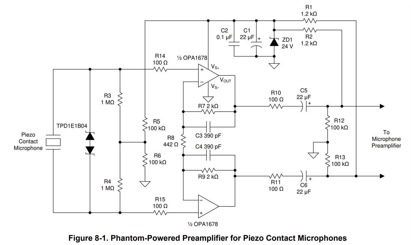
The OPA1678 can do this however I have provided additional examples since I don't know much information regarding the application. If you need further assistance for a specific design I would be happy to help. I would need some preliminary information.
What is the supply voltage?
Gain?
What is driving the input signal/s?
Is the input fully differential in?
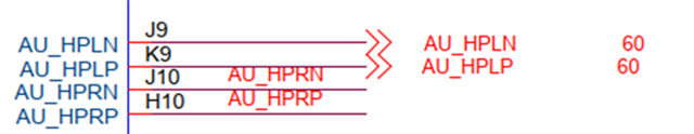
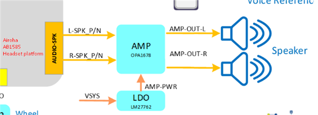
In the image above what is HPLP, HPLN?
What is the OPA1678 driving for a load?
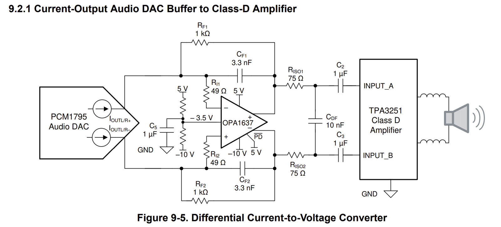
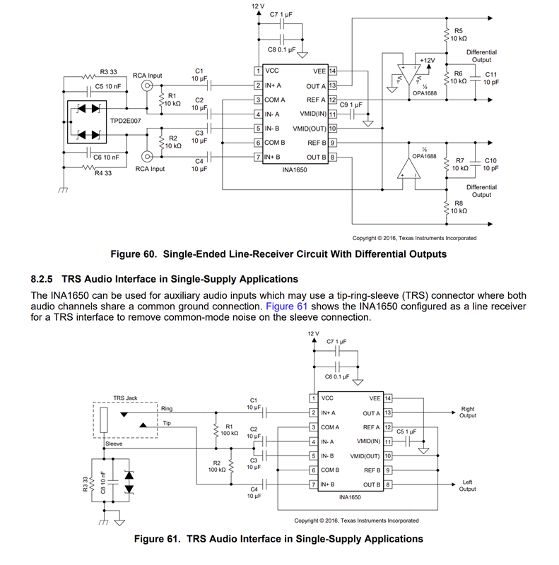
If you need a fully differential input and output we have devices such as the OPA1637 fully differential amplifier (FDA). The INA1650 could also be used.
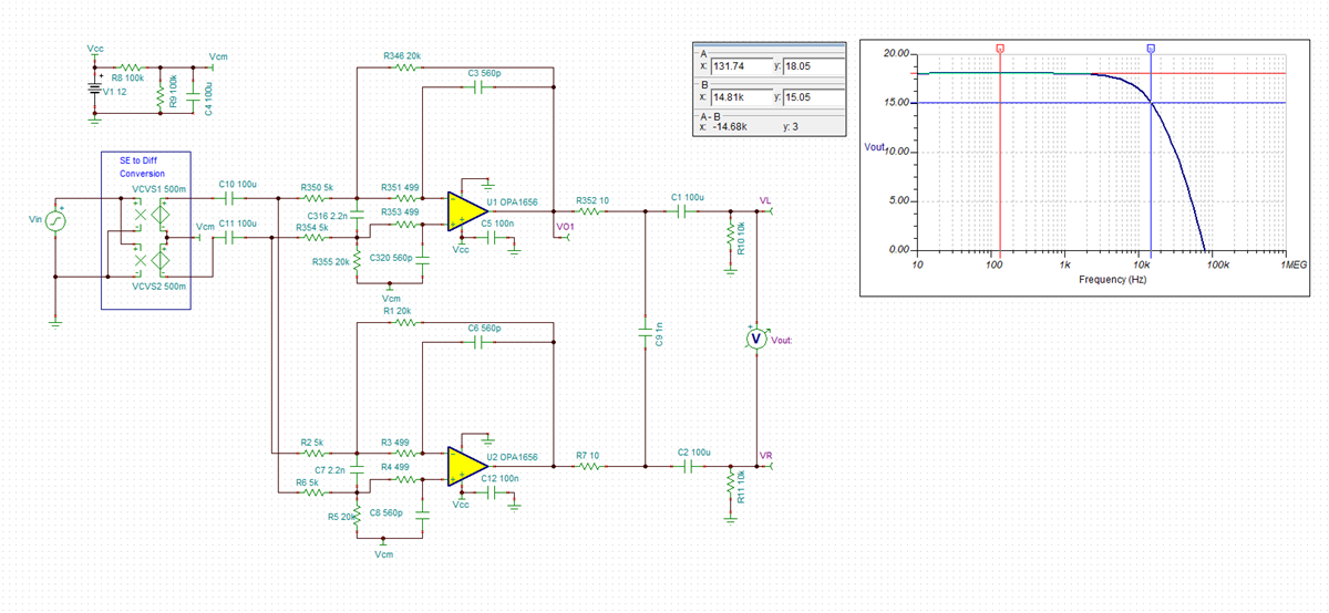
The OPA1656 may be better suited because it has more output current drive capabilities. I have put together a simulation showing a possible topology that is differential in and out. I have attached the simulation to the bottom of this post. The gain is set to 8 V/V. The gain could be adjusted by changing the feedback resistors, specifically R346 and R1. The challenge is if the gain needs to be adjustable. A potentiometer can be used however I created impedance matching on each input. If the feedback resistor is adjusted resistors R355 and R5 should also be adjusted to match the feedback resistors. This may not be an issue but I wanted to point it out.